Virtual networking has been one of the hottest areas of research and development in recent years. Kubernetes alone has, at the time of writing, 20 different networking plugins, some of which can be combined to build even more plugins. However, if we dig a bit deeper, most of these plugins and solutions are built out of two very simple constructs:
- a virtual switch - anything from a linux bridge through VPP and IOVisor to OVS
- ACL/NAT - most commonly implemented as iptables, with anything from netfilter to eBPF under the hood
Note1: for the purpose of this article I won’t consider service meshes as a network solution, although it clearly is one, simply because it operates higher than TCP/IP and ultimately still requires network plumbing to be in place
If those look familiar, you’re not mistaken, they are the same exact things that were used to connect VMs together and enforce network security policies at the dawn of SDN era almost a decade ago. Although some of these technologies have gone a long way in both features and performance, they still treat containers the same way they treated VMs. There are a few exceptions that don’t involve the above constructs, like SR-IOV, macvlan/ipvlan and running containers in host namespace, however they represent a small fraction of corner case solutions and can be safely ignored for the purpose of this discussion. That’s why for networking folk it won’t be too big a mistake to think of containers as VMs, let’s see why:
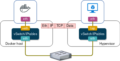
At a high level both container and VM networking are exactly the same, doesn’t matter what plugin, what networking model (CNM/CNI), what vSwitch flavour or what offload technology you use. Any virtual workload must have a virtual patch cable connecting it to a vSwitch, which implements forwarding and security policies programmed by an SDN controller. These tenets have gone unchallenged since the early days of containers and this is how I, personally, always imagined a typical virtual networking solution would look like. Until I read about AppSwitch and got so excited I decided to sign up for a beta program just to take it apart and see how it works. But before I dive deep into its architecture, I need to provide some theoretical background and I’ll do that by zooming in on a part of the (Linux) networking stack that sits right above TCP/IP.
Network Socket API
Let’s start our exploration by examining what happens when a TCP client wants to communicate with a TCP server on a remote host. The first thing that the client library does is it creates a socket by making a socket() system call for a specific address family (local, IPv4, IPv6) and transport protocol (TCP, UDP). The returned value is a file descriptor that points to a socket. This file descriptor is used in all subsequent network calls.
sockfd = socket(AF_INET, SOCK_STREAM, 0) /* Create an IPv4 TCP socket */
Next the client issues a connect() system call, where it passes the new socket file descriptor along with a pointer to serv_addr data structures that contains the destination IP and port of the TCP server.
connect(sockfd, &serv_addr, sizeof(serv_addr)) /* Returns 0 if connected */
Behind the scenes the last call initiates a TCP 3-way handshake with the remote server and returns 0 if TCP sessions transitions to the Established state.
Finally, when TCP session is established, the client interacts with the socket the same way it does with any normal file by calling read() and write() to receive and send data to the remote server.
read(sockfd, buffer, strlen(buffer))  /* Returns the number of bytes read */
write(sockfd, buffer, strlen(buffer)) /* Returns the number of bytes written */
Below is a simplified diagram that shows the above syscalls and maps them to different stages of TCP connection. Note that only the layers relevant to the purpose of this discussion are shown. For a more comprehensive overview of Linux networking stack refer to 1, 2 and 3.
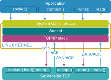
On the server side the sequence of system calls is a little different. After a server creates a socket with the socket() call, it tries to bind() to a particular IP and port number of the host:
bind(sockfd, &serv_addr, sizeof(serv_addr)) /* Returns 0 if successful */
In order to start accepting incoming TCP SYN requests, the socket needs to be marked as passive by making a listen() call, which also specifies the maximum size of a queue for pending TCP connections:
listen(sockfd, SOMAXCONN) /* Returns 0 if successful */
Once the TCP 3-way handshake with the client is complete and the connection transitions to the Established state, it will be pulled off the queue by an accept() call, running in an infinite loop, which returns a new connected socket file descriptor back to the server.
newsockfd = accept(sockfd, &client_addr, &client_len) /* Create a new socket */
The server application now proceeds to read and write data similar to the client side.
Appswitch high-level architecture
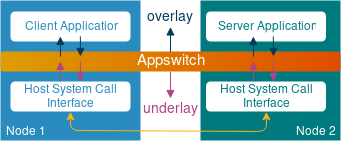
Appswitch is a distributed virtual networking solution that intercepts application’s network events at the system call interface level, before they get to the TCP/IP stack of the host. This allows it to make routing decisions and enforce security policies without the need for vSwitches or iptables. The way it abstracts host’s TCP/IP stack (underlay) from the Appswitch-managed application IP address space (overlay) is not too much dissimilar from the way traditional routing protocols operate.
Just like a typical distributed routing protocol, Appswitch builds a database of all known local endpoint addresses at each node, distributes it to other members of a cluster with itself as the next-hop, calculates how to forward connection setup calls between local and remote endpoints and uses those results to steer network traffic between them. Sounds very much like something BGP/OSPF/IS-IS would do, doesn’t it? Let’s have a closer look at the actual elements involved, using the diagram from the original Appswitch research paper:
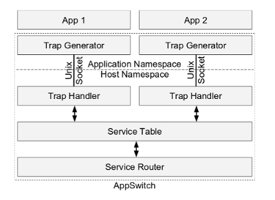
The first thing Appswitch does when it starts is neighbor discovery. The element responsible for this is a Service Router which uses Serf to efficiently discover and disseminate information in a cluster of Appswitch nodes. Serf is Hashicorp’s implementation of a gossip protocol - a cluster membership and communication protocol. Serf should be very easy to understand for those familiar with flood-and-learn behaviour of OSPF and IS-IS on broadcast multiaccess links, with the biggest distinction being that designated routers are chosen randomly and independently by each node of the link.
Whenever a new application is launched inside Appswitch, it gets moved to a dedicated network namespace, where a Trap Generator listens for network system calls and forwards them to a Trap Handler over a shared Unix domain socket. Together these two elements form the forwarding plane for network system calls. Every time an application issues a socket() syscall, the trap generator forwards it to the trap handler, which in turn creates a socket in the host namespace and passes its reference all the way back to the calling application. Once the connection is established, all read() and write() syscalls will be made using the returned sockfd, effectively achieving the same performance as if our application was running directly on host OS.
The central element in Appswitch architecture is a Service Table - a distributed, eventually consistent database which stores mappings between running applications and their next-hop transport addresses. This information is used by the Trap Handler in connect() syscall to build the serv_addr data structure with the real IP and port of the target application. In a steady state each node in an Appswitch cluster will have the same view of this database and all updates to this database will be gossiped to other members of a cluster by a Service Router.
Appswitch detailed overview
Let’s have a closer look at what happens at different stages of Appswitch lifecycle.
1. Installation and Startup
At the time of writing Appswitch is being distributed as a docker container hosted in a private docker repository on docker hub (access provided based on request). It contains a single binary executable called ax which needs to be started in PID and network namespaces of the host in order to be able to talk to host’s syscall interface and track application threads. By default, Appswitch attaches to the TCP/IP stack of the host in two ways:
- It starts management REST API and Serf processes that bind to ports 6664 and 7946.
- It selects one of the host’s IP addresses and reserves a pool of ports (e.g. 40000-60000) that will be dynamically allocated to applications in response to
bind()andconnect()system calls.
2. Joining a cluster
One of the first things a running Appswitch instance has to do is discover all members of a cluster. This is accomplished by providing an IP address of at least one node of an existing cluster as a startup parameter, which is then used to discover all other members. The information exchanged during neighbor discovery phase, which includes host IPs, names and roles, gets recorded in the Service Table and can be viewed with ax get nodes command. The mechanism of neighbor discovery and monitoring inside a cluster is not Appswitch-specific so I won’t spend much time on it here, however I highly recommend reading at least the protocol overview on the official Serf website, as this is a very common approach in modern-day eventually consistent cluster architectures.
3. Cluster scale-out
A cluster is a set of nodes running Appswitch daemons that can directly communicate with one another and all use Serf to monitor state of other cluster members. Like any other cluster protocol, Serf has its limitations and Appswitch has a very neat mechanism to allow services to scale beyond a single cluster boundary, e.g. between a LAN and a WAN, called Federation. In principle, it’s somewhat similar to hierarchical BGP RR design with route reflectors doing next-hop self. A set of Appswitch nodes can be designated as Federation gateways, which allows them to propagate information about running applications between two different clusters. When doing so they change the IP/port information to point to themselves, which forces all inter-cluster traffic to go via one of these nodes.
4. Registering a server application
Once Appswitch instance has joined a cluster, it’s ready to onboard its first application. Let’s start with a web server that needs to be accessible from other Appswitch-managed applications (East-West) and externally (North-South). When starting a server application, we need to provide a unique identifier that will be used by other endpoints to reach it. That identifier can be either an IP address (provided with --ip argument) or a hostname (provided with --name argument). If only hostname is specified, IP address will still be allocated behind the scenes and Appswitch will program its embedded DNS to make sure all other applications can reach our web server by its name.
Moments after it’s been started, the web server issues a bind() syscall, specifying the IP/port it wants to bind to, which gets intercepted by the trap generator and forwarded to the trap handler. The latter generates another bind() syscall, however the new bind() has two notable differences:
- It contains the host IP and one of the reserved ports (40000 - 60000) specified at the startup
- It’s destined towards a host’s syscall interface
The resulting mappings between the internal socket address of the web server, the overlay IP address assigned to it by the Appswitch and the “real” or underlay address of the host get recorded in the Service Table and gossiped to all other members of the cluster.
3. Processing client requests
Now let’s see what happens when another Appswitch application tries to connect to the previously started web server. The client may try to connect to the web server by its hostname, assuming the server was configured with one, in which case the DNS request will get handled by an embedded DNS server running on all Appswitch nodes, as a part of the same binary that runs service table and service router, and the client library will receive the overlay IP address of the web server.
As soon as the connect() syscall gets intercepted by the Trap Generator and forwarded to the Trap Handler, the latter consults the local Service Table and finds an entry for the web server, which was previously broadcasted to all members of the cluster. This is also a point at which Appswitch performs security isolation and load balancing:
It checks whether security zone of a client matches the one of the server and only proceeds if they are the same. This allows users to split application into different security groups and enforce isolation between them without the need for any dataplane ACLs
It also determines which exact server to include in the
connect()syscall, in case multiple servers have registered with the same IP or hostname. This provides a fully-distributed client-side load-balancing solution without the need for any middleware.
Once all the checks have passed and a destination server has been determined, Trap Handler issues a connect() syscall with the underlay IP and port of that server app. At the end of the 3-way TCP handshake the connect() call returns 0 and the two applications continue to read() and write() using the sockfd provided by Appswitch, as if they were running directly in host network namespace.
4. Ingress forwarding
When starting a server-side application, we have an option to make it available externally to clients outside of an Appswitch cluster, by mapping a server port to an arbitrary port of the host. This is accomplished with an --expose INSIDE:OUTSIDE argument, which will map the INSIDE application port to a specified OUTSIDE port on the host. We can also simulate the behaviour of k8s NodePort by changing this argument to --expose INSIDE:0.0.0.0:OUTSIDE, which will expose the same port on ALL members of an Appswitch cluster.
5. Egress forwarding
All outbound client-side syscalls that don’t find a match in the local Service Table, will be forwarded to one of the Egress Gateway nodes. Any number of Appswitch instances can be designated as Egress Gateway nodes at startup, which makes them pick a random port from a reserved pool, broadcast their presence to the rest of the cluster and start listening for incoming connections from other members. When the client-side Trap Handler intercepts the connect() syscall to an external service, it tweaks the address and sends it to one of the egress gateways instead. At the same time it communicates the real external service address to the egress gateway out-of-band. When the egress gateway receives the external service address, it will splice the two TCP sessions together connecting the Appswitch application to its intended external destination.
Demo
Finally, the time has come for the proof of the pudding. To demonstrate how Appswitch works in real life I’ll use the famous Docker voting app - a simple application comprised of 5 (micro)services that all interact over standard APIs. To make it more realistic, I’ll split the voting app between two Docker hosts to demonstrate how different parts of the same application are able to communicate remotely, assisted by Appswitch. The following diagram shows how different application components are mapped to a pair docker hosts.
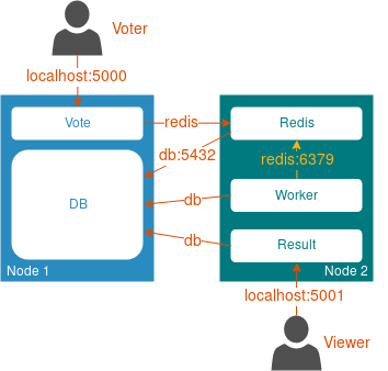
Unlike the original voting app diagram which shows the flow of data within the app, the arrows in the diagram above show the direction and destination of the initial TCP SYN, which will be important for the following explanation.
Note that in the demo we’ll deploy all necessary components manually, using
docker-composeanddocker runcommands, which doesn’t mean the same can’t be done by an orchestrator. One of the goals of this demo is to be easy to reproduce and understand and I felt like using k8s would make it more confusing and distract the reader from the main point. For demonstration of how to use Appswitch inside k8s environment refer to the official integration manual.
1. Installation
In order to deploy all 5 components of this app, I’ll use two docker-compose files, which are based on the original docker-compose file, with a few modifications to make them work with Appswitch:
- The command argument is now prepended with
/usr/bin/ax run, which is an Appswitch wrapper that containts the Trap Generator to tracks the network system calls - Network mode is set to none - we won’t need any network interface inside a Docker container whatsoever
- Volumes now include three additional items:
- /var/run/appswitch - a communication channel between a trap generator running inside a container and a trap handler running in the host namespace
- /usr/bin/ax - an Appswitch binary made available inside a container
- /etc/resolv.conf - overrides container DNS settings to redirect queries to an embedded Appswitch DNS service.
These two docker-compose files are stored in my personal fork of the voting app and are the only thing that is different between my fork and the original repo. So the first step is to download the voting app:
git clone https://github.com/networkop/example-voting-app.git ax; cd ax
To be able to run everything on a single laptop, I simulate docker hosts by running Docker daemon inside a Docker container, a pattern commonly known as docker-in-docker or dind. Additionally I expose the Docker API ports of the two dind containers to be able to manage them from my host OS.
docker run -d --privileged --name worker-1 --hostname=worker-1 \
-p 5000:5000 -p 12375:2375 \
-v /usr/local/bin/docker-compose:/usr/local/bin/docker-compose \
-v $(pwd):$(pwd) \
docker:stable-dind

docker run -d --privileged --name worker-2 --hostname=worker-2 \
-p 5001:5001 -p 22375:2375 \
-v /usr/local/bin/docker-compose:/usr/local/bin/docker-compose \
-v $(pwd):$(pwd) \
docker:stable-dind
These two commands will create a simple two-node topology as shown below:
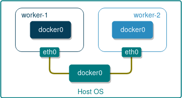
Each docker host will have its own unique IP assigned to interface eth0 and will most likely have the same IP assigned to internal docker0 bridge. We can safely ignore the latter since docker bridge is not used by Appswitch, however we would need to know the IPs assigned to eth0 in order to be able to bootstrap the Serf cluster.
export IP_1=$(docker inspect worker-1 -f "{{ .NetworkSettings.Networks.bridge.IPAddress }}")
export IP_2=$(docker inspect worker-2 -f "{{ .NetworkSettings.Networks.bridge.IPAddress }}")
Next, on each node we need to start an Appswitch daemon and pass the above IPs as input parameters.
docker --host=localhost:12375 run -d --name=ax \
--pid=host `# To identify and track application threads from host namespace` \
--net=host `# To make host network available for the application` \
--privileged `# To set seccomp filter` \
-v /usr/bin:/hostbin `# To install ax to /hostbin/` \
-v /var/run/appswitch:/var/run/appswitch `# To share the UNIX socket between app and ax daemon` \
-e AX_NODE_INTERFACE=${IP_1} `# Make sure the right IP is selected`\
-e AX_NEIGHBORS=${IP_2} `# IP of peer container`\
docker.io/appswitch/ax `# Starting the main process`

docker --host=localhost:22375 run -d --name=ax \
--pid=host `# To identify and track application threads from host namespace` \
--net=host `# To make host network available for the application` \
--privileged `# To set seccomp filter` \
-v /usr/bin:/hostbin `# To install ax to /hostbin/` \
-v /var/run/appswitch:/var/run/appswitch `# To share the UNIX socket between app and ax daemon` \
-e AX_NODE_INTERFACE=${IP_2} `# Make sure the right IP is selected`\
-e AX_NEIGHBORS=${IP_1} `# IP of peer container`\
docker.io/appswitch/ax `# Starting the main process`
At this point our Appswitch cluster should be bootstrapped and fully functional, which we can verify by listing its members from either one of the worker nodes:
docker exec -it worker-1 ax get nodes
    NAME     CLUSTER       IP      EXTERNALIP    ROLE     APPCOUNT
------------------------------------------------------------------
  worker-1  appswitch  172.17.0.2              [compute]  0
  worker-2  appswitch  172.17.0.3              [compute]  0
Now the only thing that is left is to deploy our voting app using docker compose:
docker-compose --host localhost:12375 --file ./docker-compose-1.yml up -d
docker-compose --host localhost:22375 --file ./docker-compose-2.yml up -d
A few minutes later the voting side of the app should become available on localhost:5000, while the results can be viewed on localhost:5001.You can put in more votes for cats or dogs by using “a” or “b” in the following command:
curl -sS -X POST --data "vote=a" http://localhost:5000 > /dev/null
2. Verification
Now let’s examine how Appswitch has managed to establish connectivity between all components of our voting app. The two internal server-side components are DB and Redis, and all client-side apps (vote, worker and result) are expecting to connect to them by using their respective hostnames - db and redis. Appswitch enables that by running an embedded DNS server which gets programmed with hostnames based on the --name argument of ax run command, as shown in the following snippet from the Redis service in docker-compose-1.yml:
command: /usr/bin/ax run --name redis redis-server
Embedded DNS server returns the overlay IP assigned to Redis, which will be used later by client-side apps in their syscalls. In our case we didn’t specify this IP explicitly, so Appswitch picked a random IP address which can be viewed with ax get apps command:
| Name | APPID | NODEID | CLUSTER | APPIP | DRIVER | LABELS | ZONES |
|---|---|---|---|---|---|---|---|
| redis | f00005bb | worker-2 | appswitch | 10.244.17.175 | user | zone=default | [zone==default] |
| db | f00004cd | worker-1 | appswitch | 10.12.33.253 | zone=default | [zone==default] |
As soon as DB and Redis are fully initialised and issue a listen() syscall, Appswitch broadcasts the overlay-underlay address mapping to all other members of a cluster, so that each node ends up with an identical view of this table:
| Name | CLUSTER | APPID | PROTO | SERVICEADDR | IPV4ADDR |
|---|---|---|---|---|---|
| worker-2 | appswitch | f00005b9 | tcp | redis:6379 | 172.17.0.3:40000 |
| worker-1 | appswitch | f000056d | tcp | db:5432 | 172.17.0.2:40001 |
Now, when a client-side app decides to establish a TCP session with redis on port 6379, it tries to connect() to 10.244.17.175:6379, which makes the Trap Handler issue a new connect() to 172.17.0.3:40000, the real/underlay address of redis on worker-2 node.
At the same time we have two client-side apps that act as server-side apps for external connections - vote and result. Both of these apps were started with their internal http ports exposed, like in the following example from the vote service:
command: /usr/bin/ax run --expose 80:5000 python app.py
When they attempt to bind() to port 80, Appswitch will not try to use the dynamic port range and will try to bind to the port specified in the expose command instead:
| Name | CLUSTER | APPID | PROTO | SERVICEADDR | IPV4ADDR |
|---|---|---|---|---|---|
| worker-1 | appswitch | f00004cc | tcp | 172.17.0.2:80 | 172.17.0.2:5000 |
| worker-2 | appswitch | f0000627 | tcp | 172.17.0.3:80 | 172.17.0.3:5001 |
This port mapping will only make these ports available inside their respective docker hosts, which is why we’ve exposed ports 5000 and 5001 when starting dind containers earlier.
| CONTAINER ID | IMAGE | COMMAND | CREATED | STATUS | PORTS | NAMES |
|---|---|---|---|---|---|---|
| 303d5ae4d63d | docker:stable-dind | “dockerd-entrypoint.…” | 12 hours ago | Up 7 hours | 0.0.0.0:5001->5001/tcp, 0.0.0.0:22375->2375/tcp | worker-2 |
| 2421e7556bc1 | docker:stable-dind | “dockerd-entrypoint.…” | 12 hours ago | Up 7 hours | 0.0.0.0:5000->5000/tcp, 0.0.0.0:12375->2375/tcp | worker-1 |
So a TCP SYN towards localhost:5000 will get PAT’ed by Docker-managed iptables of the Docker host, will hit the TCP/IP stack of the worker-1 node, which, once the handshake is complete, will issue an accept() syscall towards a Trap Handler and ultimately towards port 80 of the vote app.
Outro
The reason why I called this article “Serverless SDN” is because I find this to be a rather fitting description of what Appswitch is. Just like serverless computing, which abstracts away the underlying OS and server management, Appswitch abstracts away the networking stack of the host and provides networking abstractions at a well-defined socket layer. Reading through the official documentation and Appswitch research paper, I can’t get rid of the thought that this is what container networking should have looked like in the first place - not linux bridges and veth pairs and not even macvlan and ipvlan devices. The original goal of containers was to encapsulate a single process and in majority of cases that single process does not need to have a full TCP/IP stack with its own interface, IP address, MAC address - all what it cares about is sending and receiving data - and this is exactly what Appswitch provides.