Table of Contents
OpenStack - virtual network topology
In the previous post we have installed OpenStack and created a simple virtual topology as shown below. In OpenStack’s data model this topology consists of the following elements:
- Network defines a virtual L2 broadcast domain
- Subnet attached to the network, defines an IP subnet within the network
- Router provides connectivity between all directly connected subnets
- Port VM’s point of attachment to the subnet

So far nothing unusual, this is a simple Neutron data model, all that information is stored in Neutron’s database and can be queried with neutron CLI commands.
OVN Northbound DB - logical network topology
Every call to implement an element for the above data model is forwarded to OVN ML2 driver as defined by the mechanism driver setting of the ML2 plugin. This driver is responsible for the creation of an appropriate data model inside the OVN Northbound DB. The main elements of this data model are:
- Switch equivalent of a Neutron’s Subnet, enables L2 forwarding for all attached ports
- Distributed Router provides distributed routing between directly connected subnets
- Gateway Router provides connectivity between external networks and distributed routers, implements NAT and Load Balancing
- Port of a logical switch, attaches VM to the switch
This is a visual representation of our network topology inside OVN’s Northbound DB, built based on the output of ovn-nbctl show command:

This topology is pretty similar to Neutron’s native data model with the exception of a gateway router. In OVN, a gateway router is a special non-distributed router which performs functions that are very hard or impossible to distribute amongst all nodes, like NAT and Load Balancing. This router only exists on a single compute node which is selected by the scheduler based on the ovn_l3_scheduler setting of the ML2 plugin. It is attached to a distributed router via a point-to-point /30 subnet defined in the ovn_l3_admin_net_cidr setting of the ML2 plugin.
Apart from the logical network topology, Northbound database keeps track of all QoS, NAT and ACL settings and their parent objects. The detailed description of all tables and properties of this database can be found in the official Northbound DB documentation.
OVN Southbound DB - logical flows
OVN northd process running on the controller node translates the above logical topology into a set of tables stored in Southbound DB. Each row in those tables is a logical flow and together they form a forwarding pipeline by stringing together multiple actions to be performed on a packet. These actions range from packet drop through packet header modification to packet output. The stringing is implemented with a special next action which moves the packet one step down the pipeline starting from table 0. Let’s have a look at the simplified versions of L2 and L3 forwarding pipelines using examples from our virtual topology.
L2 datapath
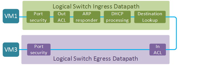
In the first example we’ll explore the L2 datapath between VM1 and VM3. Both VMs are attached to the ports of the same logical switch. The full datapath of a logical switch consists of two parts - ingress and egress datapath (the direction is from the perspective of a logical switch). The ultimate goal of an ingress datapath is to determine the output port or ports (in case of multicast) and pass the packet to the egress datapath. The egress datapath does a few security checks before sending the packet out to its destination. Two things are worth noting at this stage:
- The two datapaths can be located either on the same or on two different hypervisor nodes. In the latter case, the packet is passed between the two nodes in an overlay tunnel.
- The egress datapath does not have a destination lookup step which means that all information about the output port MUST be supplied by the ingress datapath. This means that destination lookup does not have to be done twice and it also has some interesting implications on the choice of encapsulation protocol as we’ll see in the next section.
Let’s have a closer look at each of the stages of the forwarding pipeline. I’ll include snippets of logical flows demonstrating the most interesting behaviour at each stage. Full logical datapath is quite long and can be viewed with ovn-sbctl lflow-list [DATAPATH] command. Here is some useful information, collected from the Northbound database, that will be used in the examples below:
| VM# | IP | MAC | Port UUID |
|---|---|---|---|
| VM1 | 10.0.0.2 | fa:16:3e:4f:2f:b8 | 26c23a54-6a91-48fd-a019-3bd8a7e118de |
| VM3 | 10.0.0.5 | fa:16:3e:2a:60:32 | 5c62cfbe-0b2f-4c2a-98c3-7ee76c9d2879 |
- Port security - makes sure that incoming packet has the correct source MAC and IP addresses.
table=0 (ls_in_port_sec_l2), priority=50, match=(inport == "26c23a54-6a91-48fd-a019-3bd8a7e118de"
  && eth.src == {fa:16:3e:4f:2f:b8}), action=(next;)
table=1 (ls_in_port_sec_ip), priority=90, match=(inport == "26c23a54-6a91-48fd-a019-3bd8a7e118de"
  && eth.src == fa:16:3e:4f:2f:b8 && ip4.src == {10.0.0.2}), action=(next;)
- Egress ACL - set of tables that implement Neutron’s Egress Port Security functionality. Default rules allow all egress traffic from a VM. The first flow below matches all new connections coming from VM1 and marks them for connection tracking with
reg0[1] = 1. The next table catches these marked packets and commits them to the connection tracker. Specialct_label=0/1action ensures return traffic is allowed which is a standard behaviour of all stateful firewalls.
table=6 (ls_in_acl), priority=2002 , match=(((ct.new && !ct.est) ||
  (!ct.new && ct.est && !ct.rpl && ct_label.blocked == 1)) &&
  (inport == "26c23a54-6a91-48fd-a019-3bd8a7e118de" && ip4)),
  action=(reg0[1] = 1; next;)
table=9 (ls_in_stateful), priority=100  , match=(reg0[1] == 1),
  action=(ct_commit(ct_label=0/1); next;)
- ARP Responder - matches an incoming ARP/ND request and generates an appropriate ARP/ND response. The way it is accomplished is similar to Neutron’s native ARP responder feature. Effectively an ARP request gets transformed into an ARP response by swapping source and destination fields.
table=10(ls_in_arp_rsp), priority=50, match=(arp.tpa == 10.0.0.5 && arp.op == 1),
  action=(eth.dst = eth.src; eth.src = fa:16:3e:2a:60:32; arp.op = 2; /* ARP reply */
  arp.tha = arp.sha; arp.sha = fa:16:3e:2a:60:32; arp.tpa = arp.spa; arp.spa = 10.0.0.5;
  outport = inport; flags.loopback = 1; output;)
- DHCP Processing - set of tables that implement the DHCP server functionality using the approach similar to the ARP responder described above.
table=12(ls_in_dhcp_response), priority=100, match=(inport == "26c23a54-6a91-48fd-a019-3bd8a7e118de"
  && eth.src == fa:16:3e:4f:2f:b8 && ip4.src == 0.0.0.0 && ip4.dst == 255.255.255.255
  && udp.src == 68 && udp.dst == 67 && reg0[3]),
  action=(eth.dst = eth.src; eth.src = fa:16:3e:94:b6:bc; ip4.dst = 10.0.0.2;
  ip4.src = 10.0.0.1; udp.src = 67; udp.dst = 68; outport = inport; flags.loopback = 1; output;)
- Destination Lookup - implements L2 forwarding based on the destination MAC address of a frame. At this stage the outport variable is set to the VM3’s port UUID.
table=13(ls_in_l2_lkup), priority=50, match=(eth.dst == fa:16:3e:2a:60:32),
  action=(outport = "5c62cfbe-0b2f-4c2a-98c3-7ee76c9d2879"; output;)
- Ingress ACL - set of tables that implement Neutron’s Ingress Port security. For the sake of argument let’s assume that we have enabled inbound SSH connections. The principle is same as before - the packet gets matched in one table and submitted to connection tracking in another table.
table=4 (ls_out_acl), priority=2002 , match=(((ct.new && !ct.est)
  || (!ct.new && ct.est && !ct.rpl && ct_label.blocked == 1))
  && (outport == "26c23a54-6a91-48fd-a019-3bd8a7e118de" && ip4
  && ip4.src == 0.0.0.0/0 && tcp && tcp.dst == 22)),
  action=(reg0[1] = 1; next;
table=6 (ls_out_stateful), priority=100  , match=(reg0[1] == 1),
  action=(ct_commit(ct_label=0/1); next;)
- Port Security - implements inbound port security for destination VM by checking the sanity of destination MAC and IP addresses.
table=7 (ls_out_port_sec_ip), priority=90, match=(outport == "5c62cfbe-0b2f-4c2a-98c3-7ee76c9d2879"
  && eth.dst == fa:16:3e:2a:60:32 && ip4.dst == {255.255.255.255, 224.0.0.0/4, 10.0.0.5}),
  action=(next;)
table=8 (ls_out_port_sec_l2), priority=50, match=(outport == "5c62cfbe-0b2f-4c2a-98c3-7ee76c9d2879"
  && eth.dst == {fa:16:3e:2a:60:32}),
  action=(output;)
L3 datapath
Similar to a logical switch pipeline, L3 datapath is split into ingress and egress parts. In this example we’ll concentrate on the Gateway router datapath. This router is connected to a distributed logical router via a transit subnet (SWtr) and to an external network via an external bridge (SWex) and performs NAT translation for all VM traffic.
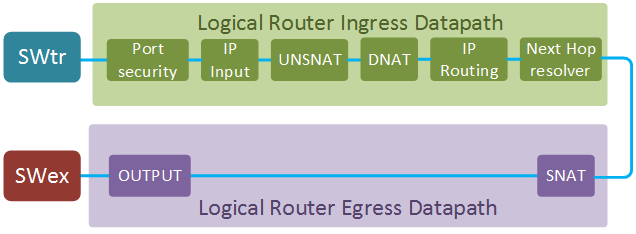
Here is some useful information about router interfaces and ports that will be used in the examples below.
| SW function | IP | MAC | Port UUID |
|---|---|---|---|
| External | 169.254.0.54/24 | fa:16:3e:39:c8:d8 | lrp-dc1ae9e3-d8fd-4451-aed8-3d6ddc5d095b |
| DVR-GW transit | 169.254.128.2/30 | fa:16:3e:7e:96:e7 | lrp-gtsp-186d8754-cc4b-40fd-9e5d-b0d26fc063bd |
- Port security - implements sanity check for all incoming packets.
table=0 (lr_in_admission), priority=50, match=((eth.mcast || eth.dst == fa:16:3e:7e:96:e7)
 && inport == "lrp-gtsp-186d8754-cc4b-40fd-9e5d-b0d26fc063bd"), action=(next;)
IP Input - performs additional L3 sanity checks and implements typical IP services of a router (e.g. ICMP/ARP reply)
table=1 (lr_in_ip_input), priority=100, match=(ip4.src == {169.254.128.2, 169.254.128.3}),
action=(drop;)
table=1 (lr_in_ip_input), priority=90, match=(inport == "lrp-gtsp-186d8754-cc4b-40fd-9e5d-b0d26fc063bd"
&& arp.tpa == 169.254.128.2 && arp.op == 1),
action=(eth.dst = eth.src; eth.src = fa:16:3e:7e:96:e7; arp.op = 2;
/* ARP reply */ arp.tha = arp.sha; arp.sha = fa:16:3e:7e:96:e7;
arp.tpa = arp.spa; arp.spa = 169.254.128.2;
outport = "lrp-gtsp-186d8754-cc4b-40fd-9e5d-b0d26fc063bd"; flags.loopback = 1; output;)
table=1 (lr_in_ip_input), priority=90, match=(ip4.dst == 169.254.128.2
&& icmp4.type == 8 && icmp4.code == 0),
action=(ip4.dst <-> ip4.src; ip.ttl = 255; icmp4.type = 0; flags.loopback = 1; next; )
UNSNAT - translates the destination IP to the real address for packets coming from external networks
table=3 (lr_in_unsnat), priority=100, match=(ip && ip4.dst == 169.254.0.54),
action=(ct_snat; next;)
DNAT - implements what is commonly known as static NAT, i.e. performs one-to-one destination IP translation for every configured floating IP.
table=4 (lr_in_dnat), priority=100, match=(ip && ip4.dst == 169.254.0.52),
action=(flags.loopback = 1; ct_dnat(10.0.0.5);)
IP routing - implements L3 forwarding based on the destination IP address. At this stage the
outportis decided, IP TTL is decremented and the new next-hop IP is set in register0.
table=5 (lr_in_ip_routing), priority=1, match=(ip4.dst == 0.0.0.0/0),
  action=(ip.ttl--; reg0 = 169.254.0.1; reg1 = 169.254.0.54; eth.src = fa:16:3e:39:c8:d8;
  outport = "lrp-dc1ae9e3-d8fd-4451-aed8-3d6ddc5d095b"; flags.loopback = 1; next;)
Next Hop Resolver - discovers the next-hop MAC address for a packet. This could either be a statically configured value when the next-hop is an OVN-managed router or a dynamic binding learned through ARP and stored in a special
MAC_Bindingtable of Southbound DB.table=6 (lr_in_arp_resolve), priority=100, match=(outport == "lrp-gtsp-186d8754-cc4b-40fd-9e5d-b0d26fc063bd" && reg0 == 169.254.128.1), action=(eth.dst = fa:16:3e:2a:7f:25; next;) table=6 (lr_in_arp_resolve), priority=0, match=(ip4), action=(get_arp(outport, reg0); next;)SNAT - implements what is commonly known as overload NAT. Translates source IP, source UDP/TCP port number and ICMP Query ID to hide them behind a single IP address
table=0 (lr_out_snat), priority=25, match=(ip && ip4.src == 10.0.0.0/24),
  action=(ct_snat(169.254.0.54);)
- Output - send the packet out the port determined during the IP routing stage.
table=1 (lr_out_delivery), priority=100, match=(outport == "lrp-gtsp-186d8754-cc4b-40fd-9e5d-b0d26fc063bd"),
  action=(output;)
This was a very high-level, abridged and simplified version of how logical datapaths are built in OVN. Hopefully this lays enough groundwork to move on to the official northd documentation which describes both L2 and L3 datapaths in much greater detail.
Apart from the logical flows, Southbound DB also contains a number of tables that establish the logical-to-physical bindings. For example, the Port_Binding table establishes binding between logical switch, logical port, logical port overlay ID (a.k.a. tunnel key) and the unique hypervisor ID. In the next section we’ll see how this information is used to translate logical flows into OpenFlow flows at each compute node. For full description of Southbound DB, its tables and their properties refer to the official SB schema documentation.
OVN Controller - OpenFlow flows
OVN Controller process is the distributed part of OVN SDN controller. This process, running on each compute node, connects to Southbound DB via OVSDB and configures local OVS according to information received from it. It also uses Southbound DB to exchange the physical location information with other hypervisors. The two most important bits of information that OVN controller contributes to Southbound DB are physical location of logical ports and overlay tunnel IP address. These are the last two missing pieces to map logical flows to physical nodes and networks.
The whole flat space of OpenFlow tables is split into multiple areas. Tables 16 to 47 implement an ingress logical pipeline and tables 48 to 63 implement an egress logical pipeline. These tables have no notion of physical ports and are functionally equivalent to logical flows in Southbound DB. Tables 0 and 65 are responsible for mapping between the physical and logical realms. In table 0 packets are matched on the physical incoming port and assigned to a correct logical datapath as was defined by the Port_Binding table. In table 65 the information about the outport, that was determined during the ingress pipeline processing, is mapped to a local physical interface and the packet is sent out.
To demonstrate the details of OpenFlow implementation, I’ll use the traffic flow between VM1 and external destination (8.8.8.8). For the sake of brevity I will only cover the major steps of packet processing inside OVS, omitting security checks and ARP/DHCP processing.

When packets traverse OpenFlow tables they get labelled or annotated with special values to simplify matching in subsequent tables. For example, when table 0 matches the incoming port, it annotates the packet with the datapath ID. Since it would have been impractical to label packets with globally unique UUIDs from Soutbound DB, these UUIDs get mapped to smaller values called tunnel keys. To make things even more confusing, each port will have a local kernel ID, unique within each hypervisor. We’ll need both tunnel keys and local port IDs to be able to track the packets inside the OVS. The figure below depicts all port and datapath IDs that have been collected from the Soutbound DB and local OVSDB on each hypervisor. Local port numbers are attached with a dotted line to their respective tunnel keys.

When VM1 sends the first packet to 8.8.8.8, it reaches OVS on local port 13. OVN Controller knows that this port belongs to VM1 and installs an OpenFlow rule to match all packets from this port and annotate them with datapath ID (OXM_OF_METADATA), incoming port ID (NXM_NX_REG14), conntrack zone (NXM_NX_REG13). It then moves these annotated packets to the first table of the ingress pipeline.
table=0, priority=100,in_port=13 actions=load:0x2->NXM_NX_REG13[],
  load:0x2->OXM_OF_METADATA[],load:0x2->NXM_NX_REG14[],
  resubmit(,16)
Skipping to the L2 MAC address lookup stage, the output port (0x1) is decided based on the destination MAC address and saved in register 15.
table=29, priority=50,metadata=0x2,dl_dst=fa:16:3e:0d:df:ea
  actions=load:0x1->NXM_NX_REG15[],resubmit(,32)
Finally, the packet reaches the last table where it is sent out the physical patch port interface towards R1.
table=65, priority=100,reg15=0x1,metadata=0x2 actions=output:1
The other end of this patch port is connected to a local instance of distributed router R1. That means our packet, unmodified, re-enters OpenFlow table 0, only this time on a different port. Local port 2 is associated with a logical pipeline of a router, hence metadata for this packet is set to 4.
table=0, priority=100,in_port=2 actions=load:0x4->OXM_OF_METADATA[],
  load:0x1->NXM_NX_REG14[],resubmit(,16)
The packet progresses through logical router datapath and finally gets to table 21 where destination IP lookup take place. It matches the catch-all default route rule and the values for its next-hop IP (0xa9fe8002), MAC address (fa:16:3e:2a:7f:25) and logical output port (0x03) are set.
table=21, priority=1,ip,metadata=0x4 actions=dec_ttl(),load:0xa9fe8002->NXM_NX_XXREG0[96..127],
  load:0xa9fe8001->NXM_NX_XXREG0[64..95],mod_dl_src:fa:16:3e:2a:7f:25,
  load:0x3->NXM_NX_REG15[],load:0x1->NXM_NX_REG10[0],resubmit(,22)
Table 65 converts the logical output port 3 to physical port 6, which is yet another patch port connected to a transit switch.
table=65, priority=100,reg15=0x3,metadata=0x4 actions=output:6
The packet once again re-enters OpenFlow pipeline from table 0, this time from port 5. Table 0 maps incoming port 5 to the logical datapath of a transit switch with Tunnel key 7.
table=0, priority=100,in_port=5 actions=load:0x7->OXM_OF_METADATA[],
  load:0x1->NXM_NX_REG14[],resubmit(,16)
Destination lookup determines the output port (2) but this time, instead of entering the egress pipeline locally, the packet gets sent out the physical tunnel port (7) which points to the IP address of a compute node hosting the GW router. The headers of an overlay packet are populated with logical datapath ID (0x7), logical input port (copied from register 14) and logical output port (0x2).
table=29, priority=50,metadata=0x7,dl_dst=fa:16:3e:7e:96:e7
  actions=load:0x2->NXM_NX_REG15[],resubmit(,32)
table=32, priority=100,reg15=0x2,metadata=0x7 actions=load:0x7->NXM_NX_TUN_ID[0..23],
  set_field:0x2/0xffffffff->tun_metadata0,move:NXM_NX_REG14[0..14]->NXM_NX_TUN_METADATA0[16..30],
  output:7
When packet reaches the destination node, it once again enters the OpenFlow table 0, but this time all information is extracted from the tunnel keys.
table=0, priority=100,in_port=17 actions=move:NXM_NX_TUN_ID[0..23]->OXM_OF_METADATA[0..23],
  move:NXM_NX_TUN_METADATA0[16..30]->NXM_NX_REG14[0..14],
  move:NXM_NX_TUN_METADATA0[0..15]->NXM_NX_REG15[0..15],
  resubmit(,33)
At the end of the transit switch datapath the packet gets sent out port 12, whose peer is patch port 16.
table=65, priority=100,reg15=0x2,metadata=0x7 actions=output:12
The packet re-enters OpenFlow table 0 from port 16, where it gets mapped to the logical datapath of a gateway router.
table=0, priority=100,in_port=16 actions=load:0x2->NXM_NX_REG11[],
  load:0x6->NXM_NX_REG12[],load:0x6->OXM_OF_METADATA[],
  load:0x2->NXM_NX_REG14[],resubmit(,16)
Similar to a distributed router R1, table 21 determines the next-hop MAC address for a packet and saves the output port in register 15.
table=21, priority=1,ip,metadata=0x6 actions=dec_ttl(),load:0xa9fe0001->NXM_NX_XXREG0[96..127],
  load:0xa9fe0036->NXM_NX_XXREG0[64..95],mod_dl_src:fa:16:3e:39:c8:d8,
  load:0x1->NXM_NX_REG15[],load:0x1->NXM_NX_REG10[0],resubmit(,22)
The first table of an egress pipeline source-NATs packets to external IP address of the GW router.
table=48, priority=33,ip,metadata=0x6,nw_src=10.0.0.2
  actions=ct(commit,table=49,zone=NXM_NX_REG12[0..15],nat(src=169.254.0.56))
The modified packet is sent out the physical port 14 towards the external switch.
table=65, priority=100,reg15=0x1,metadata=0x6 actions=output:14
External switch determines the output port connected to the br-ex on a local hypervisor and send the packet out.
table=0, priority=100,in_port=13 actions=load:0x5->NXM_NX_REG11[],
  load:0x3->NXM_NX_REG12[],load:0x3->OXM_OF_METADATA[],
  load:0x2->NXM_NX_REG14[],resubmit(,16)
table=29, priority=0,metadata=0x3 actions=load:0xfffe->NXM_NX_REG15[],resubmit(,32)
table=33, priority=100,reg15=0xfffe,metadata=0x3
  actions=load:0x1->NXM_NX_REG13[],load:0x1->NXM_NX_REG15[],
  resubmit(,34),load:0xfffe->NXM_NX_REG15[]
table=65, priority=100,reg15=0x1,metadata=0x3 actions=output:15
As we’ve just seen, OpenFlow repeats the logical topology by interconnecting logical datapaths of switches and routers with virtual point-to-point patch cables. This may seem like an unnecessary modelling element with a potential for a performance impact. However, when flows get installed in kernel datapath, these patch ports do not exist, which means that there isn’t any performance impact on packets in fastpath.
Physical network - GENEVE overlay
Before we wrap up, let us have a quick look at the new overlay protocol GENEVE. The goal of any overlay protocol is to transport all the necessary tunnel keys. With VXLAN the only tunnel key that could be transported is the Virtual Network Identifier (VNI). In OVN’s case these tunnel keys include not only the logical datapath ID (commonly known as VNI) but also both input and output port IDs. You could have carved up the 24 bits of VXLAN tunnel ID to encode all this information but this would only have given you 256 unique values per key. Some other overlay protocols, like STT have even bigger tunnel ID header size but they, too, have a strict upper limit.
GENEVE was designed to have a variable-length header. The first few bytes are well-defined fixed size fields followed by variable-length Options. This kind of structure allows software developers to innovate at their own pace while still getting the benefits of hardware offload for the fixed-size portion of the header. OVN developers decided to use Options header type 0x80 to store the 15-bit logical ingress port ID and a 16-bit egress port ID (an extra bit is for logical multicast groups).
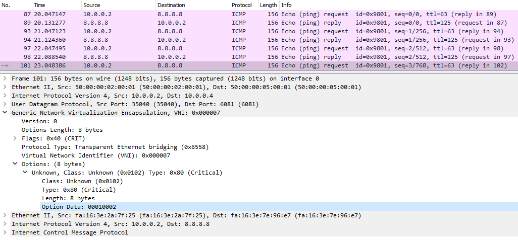
The figure above shows the ICMP ping coming from VM1(10.0.0.2) to Google’s DNS. As I’ve showed in the previous section, GENEVE is used between the ingress and egress pipelines of a transit switch (SWtr), whose datapath ID is encoded in the VNI field (0x7). Packets enter the transit switch on port 1 and leave it on port 2. These two values are encoded in the 00010002 value of the Options Data field.
So now that GENEVE has taken over as the inter-hypervisor overlay protocol, does that mean that VXLAN is dead? OVN still supports VXLAN but only for interconnects with 3rd party devices like VXLAN-VLAN gateways or VXLAN TOR switches. Rephrasing the official OVN documentation, VXLAN gateways will continue to be supported but they will have a reduced feature set due to lack of extensibility.
Conclusion
OpenStack networking has always been one of the first use cases of any new SDN controller. All the major SDN platforms like ACI, NSX, Contrail, VSP or ODL have some form of OpenStack integration. And it made sense, since native Neutron networking has always been one of the biggest pain points in OpenStack deployments. As I’ve just demonstrated, OVN can now do all of the common networking functionality natively, without having to rely on 3rd party agents. In addition to that it has a fantastic documentation, implements all forwarding inside a single OVS bridge and it is an open-source project. As an OpenStack networking solution it is still, perhaps, a few months away from being production ready - active/active HA is not supported with OVSDB, GW router scheduling options are limited, lack of native support for DNS and Metadata proxy. However I anticipate that starting from the next OpenStack release (Ocata, Feb 2017) OVN will be ready for mass deployment even by companies without an army of OVS/OpenStack developers. And when that happens there will even less need for proprietary OpenStack SDN platforms.