Current network overview
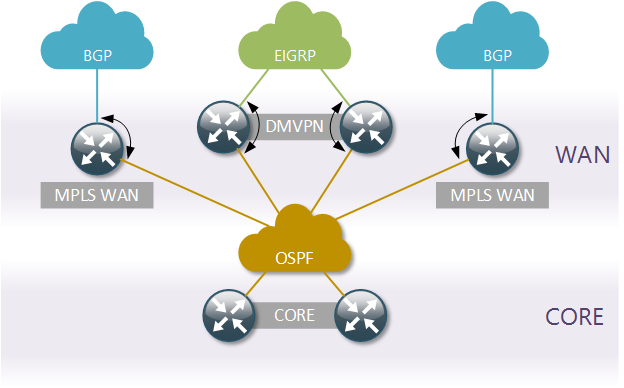
Let’s start by taking a high-level look at our DC network routing topology. The core routing protocol is OSPF, it is responsible for distributing routing information between the Core and WAN layers of the network. WAN layer consists of two MPLS L3VPN services running BGP as PE-CE protocol and two DMVPN Hubs running EIGRP. All WAN layer devices perform mutual redistribution between the respective WAN protocol and OSPF.

Target network overview
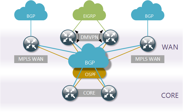
The task is to replace OSPF with BGP as the core routing protocol inside the Data Centre. There are many advantages to using BGP inside a DC, in our case they are:
- Enhanced traffic routing and filtering policies
- Reduced number of redistribution points
- Because Ivan Pepelnjak said so
We’re not going getting rid of OSPF completely, but rather reduce its function to a simple distribution of internal DC prefixes. BGP will be running on top of OSPF and distribute all the DC and WAN summary prefixes.

Physical topology overview
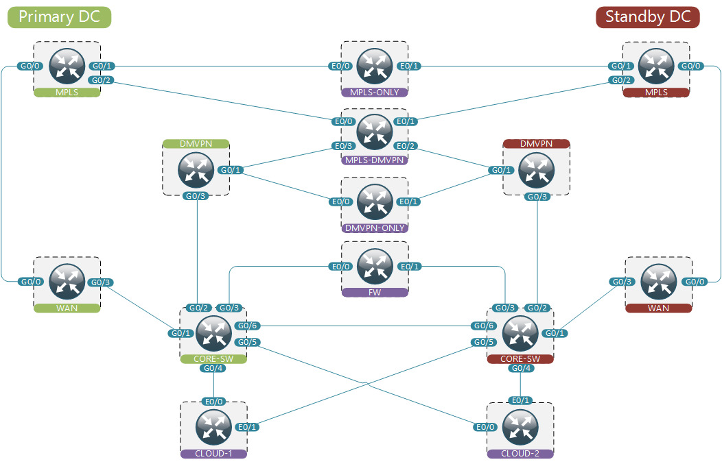
Now let’s take a closer look at the network that we’re going to emulate. All green devices on the left-hand side constitute the Active Data Centre, that is where all the traffic will flow under normal conditions. All green devices have red Standby counterparts. These devices will pick up the function of traffic forwarding in case their green peer becomes unavailable.

When simulating a real-life network it’s often impossible to fit an exact replica inside a network emulator. That’s why using mock devices is a crucial part in every simulation. The function of a mock is to approximate a set of network devices. There’s a number of mock devices on our diagram colour-coded in purple. These devices simulate the remaining parts of the network. For example, Cloud devices may represent TOR switches, while MPLS/DMVPN devices represent remote WAN sites. Normally these devices will have some made-up configuration that best reflects real life, but not necessarily a copy-paste from an existing network device.
It’s also important to pick the right amount of mock devices to strike the balance between accuracy and complexity. For example, for WAN sites it may suffice to create one site per unique combination of WAN links to make sure WAN failover works as expected.
Traffic flow definition
Let’s define how we would expect the traffic to flow through our network. Let’s assume that we should always try to use MPLS links when possible and only use DMVPN when both MPLS links are down. This translates to the following order of WAN links’ precedence:
- Primary MPLS link
- Standby MPLS link
- Primary DMVPN link
- Standby DMVPN link
Based on that we can create the following traffic flows definition for network working under normal conditions.
1 Failed None
  From FW to MPLS-DMVPN via Primary-WAN, Primary-MPLS
  From FW to DMVPN-ONLY via Primary-CORE-SW, Primary-DMVPN
  From FW to MPLS-ONLY via Primary-WAN, Primary-MPLS
  From Cloud-1 to FW Loopback0 via Primary-CORE-SW
  From Cloud-2 to MPLS-DMVPN via Primary-WAN, Primary-MPLS
We expect all traffic to flow through active devices even when the path may be suboptimal, like it’s the case with traffic from Cloud-2. Similarly, we can create traffic flows definitions for different failure conditions. The complete traffic flows definition file contains 2 additional failure scenarios covering the outage of the primary MPLS link and a complete outage of the primary core switch.
Workflow example
This is how you would approach a project like this.
- Get a copy of network-ci VM
- Get a local copy of network-ci tools
- Copy configuration from real-life devices into the config directory
- Add configuration files for mock devices to the same directory
- Review the topology definition file to make sure it reflects our physical diagram
- Review the UNL configuration file to make sure it points to the correct IP address assigned to your network-ci VM
- Kick-off topology build inside UNL by running
./0_built_topo.pyscript - Verify that traffic flows as expected with
2_test.pyscript - Start the real-time monitoring with
1_monitor.pyscript - Implement required changes on individual devices (all required changes can be found in ospf-bgp.txt file)
- Make sure that the network still behaves as before by running
2_test.pyscript - Destroy the topology in UNL by running
3_destroy_topo.py
Continuous Integration
In the previous post I’ve showed how to use Jenkins to setup the CI environment for a small demo network. The same method can be applied to setup the job for our small Data Centre. It is simply a matter of changing the directory name from acme-small to acme-large in the first build step.
Source code
All code from this and previous posts is available on Github