Building virtualised network topologies has been one of the best ways to learn new technologies and to test new designs before implementing them on a production network. There are plenty of tools that can help build arbitrary network topologies, some with an interactive GUI (e.g. GNS3 or EVE-NG/Unetlab) and some “headless”, with text-based configuration files (e.g. vrnetlab or topology-converter). All of these tools work by spinning up multiple instances of virtual devices and interconnecting them according to a user-defined topology.
Problem statement
Most of these tools were primarily designed to work on a single host. This may work well for a relatively small topology but may become a problem as the number of virtual devices grows. Let’s take Juniper vMX as an example. From the official hardware requirements page, the smallest vMX instance will require:
- 2 VMs - one for control and one for data plane
- 2 vCPUs - one for each of the VMs
- 8 GB of RAM - 2GB for VCP and 6GB for VFP
This does not include the resources consumed by the underlying hypervisor, which can easily eat up another vCPU + 2GB of RAM. It’s easy to imagine how quickly we can hit the upper limit of devices in a single topology if we can only use a single hypervisor host. Admittedly, vMX is one of the most resource-hungry virtual routers and using other vendor’s virtual devices may increase that upper limit. However, if the requirement is to simulate topologies with 100+ devices, no single server will be able to cope with the required load and a potential resource contention may lead to instabilities and various software bugs manifesting themselves in places we don’t expect.
Exploring possible solutions
Ideally, in large-scale simulations, we’d want to spread the devices across multiple hosts and interconnect them so that, from the device perspective, it’d look like they are still running on the same host. To take it a step further, we’d want the virtual links to be simple point-to-point L2 segments, without any bridges in between, so that we don’t have to deal with issues when virtual bridges consume or block some of the “unexpected” traffic, e.g. LACP/STP on Linux bridges.
Containers vs VMs
It’s possible to build multi-host VM topologies on top of a private cloud like solution like OpenStack or VMware. The operational overhead involved would be minimal as all the scheduling and network plumbing should be taken care of by virtual infrastructure manager. However this approach has several disadvantages:
- In order to not depend on the underlay, all inter-VM links would need to be implemented as overlay (VMware would require NSX)
- VMs would still be interconnected via virtual switches
- Life-cycle management of virtual topologies is not trivial, e.g. VMware requires DRS, OpenStack requires masakari
- Injecting of additional data into VMs (e.g. configuration files) requires guest OS awareness and configuration (e.g. locating and mounting of a new partition)
In contrast, containers provide an easy way to mount volumes inside a container’s filesystem, have plenty of options for resource scheduling and orchestrators and are substantially more lightweight and customizable. As a bonus, we get a unified way to package, distribute and manage lifecycle of our containers, independent from the underlying OS.
Note: AFAIK only Arista and Juniper build docker container images for their devices (cEOS and cSRX). However it is possible to run any VM-based network device inside a docker container, with many examples and makefiles available on virtnetlab.
Kubernetes vs Swarm
If we focus on Docker, the two most popular options for container orchestration would be Kubernetes and Swarm. Swarm is a Docker’s native container orchestration tool, it requires less customisation out of the box and has a simpler data model. The primary disadvantages of using Swarm for network simulations are:
- Lack of support for privileged containers (network admin (CAP_NET_ADMIN) capabilities may be required by virtualised network devices)
- Unpredictable network interface naming and order inside the container
- Docker’s main networking plugin libnetwork is opinionated and difficult to extend or modify
On the other hand, the approach chosen by K8s provides an easier way to modify the default behaviour of a network plugin or to create a completely new implementation. However, K8s itself imposes several requirements on CNI plugins:
- All containers can communicate with all other containers without NAT
- All nodes can communicate with all containers (and vice-versa) without NAT
- The IP that a container sees itself as is the same IP that others see it as
The above also implies that communication between the containers happens at L3, which means that no container should make any assumptions about the underlying L2 transport, i.e. not use any L2 protocols(apart from ARP). Another corollary of the above requirements is that every container only has a single IP and hence a single interface, which, together with the previous L2 limitation, makes network simulations in K8s nearly impossible.
Multus vs DIY
There are multiple solutions that solve the problem of a single network interface per container/pod - CNI-Genie, Knitter and Multus CNI. All of them were primarily designed for containerised VNF use cases, with the assumption that connectivity would still be provided by one of the existing plugins, which still leaves us with a number of issues:
- We have to be transparent to the underlay, so we can’t use plugins that interact with the underlay (e.g. macvlan, calico)
- Most of the CNI plugins only provide L3 connectivity between pods (e.g. flannel, ovn, calico)
- The few plugins that do provide L2 overlays (e.g contiv, weave) do not support multiple interfaces and still use virtual bridges underneath
Perhaps it would have been possible to hack one of the plugins to do what I wanted but I felt like it’d be easier to build a specialised CNI plugin to do just what I want and nothing more. As I’ve mentioned previously, developing a simple CNI plugin is not that difficult, especially if you have a clearly defined use case, which is why I’ve built meshnet - a CNI plugin to build arbitrary network topologies out of point-to-point links.
CNI plugin overview
At a very high level, every CNI plugin is just a binary and a configuration file installed on K8s worker nodes. When a pod is scheduled to run on a particular node, a local node agent (kubelet) calls a CNI binary and passes all the necessary information to it. That CNI binary connects and configures network interfaces and returns the result back to kubelet. The information is passed to CNI binary in two ways - through environment variables and CNI configuration file. This is how a CNI ADD call may look like:
CNI_COMMAND=ADD \
CNI_CONTAINERID=$id \
CNI_NETNS=/proc/$pid/ns/net \
CNI_ARGS=K8S_POD_NAMESPACE=$namepsace;K8S_POD_NAME=$name
/opt/cni/bin/my-plugin < /etc/cni/net.d/my-config
The runtime parameters get passed to the plugin as environment variables and CNI configuration file gets passed to stdin. The CNI binary runs to completion and is expected to return the configured network settings back to the caller. The format of input and output, as well as environment variables, are documented in a CNI specification document.
There are plenty of other resources that cover CNI plugin development in much greater detail, I would recommend reading at least these four:
- CNI plugins best practices
- Writing a sample CNI plugin in bash
- EVPN CNI plugin
- Workflow for writing CNI plugins
Meshnet CNI architecture
The goal of meshnet plugin is to interconnect pods via direct point-to-point links according to some user-defined topology. To do that, the plugin uses two types of links:
- veth - to interconnect pods running on the same node
- vxlan - to interconnect pods running on different nodes
One thing to note is that point-to-point links are connected directly between pods, without any software bridges in between, which makes the design a lot simpler and provides a cleaner abstraction of a physical connection between network devices.
The plugin consists of three main components:
- etcd - a private cluster storing topology information and runtime pod metadata (e.g. pod IP address and NetNS fd)
- meshnet - a CNI binary called by kubelet, responsible for pod’s network configuration
- meshnetd - a daemon responsible for Vxlan link configuration updates
Just like Multus, meshnet has the concept of master/default plugin, which sets up the first interface of the pod. This interface is setup by one of the existing plugins (e.g. bridge or flannel) and is used for pod’s external connectivity. The rest of the interfaces are setup according to a topology information stored in etcd.
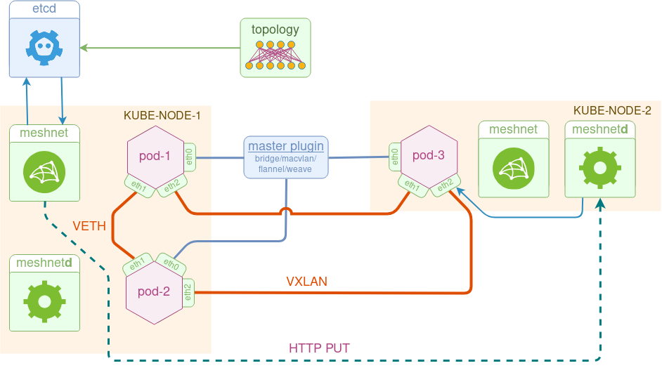
Although the original idea of a CNI plugin was to have a single stateless binary, most of the time there’s a need to maintain some runtime state (e.g. ip routes, ip allocations etc.), which is why a lot of CNI plugins have daemons. In our case, daemon’s role is to ensure Vxlan link configurations are correct across different hosts. Using the above diagram as an example, if pod-2 comes up after pod-3, there must be a way of signalling the (node-1) VTEP IP to the remote node (node-2) and making sure that the Vxlan link on node-2 is moved into pod-3’s namespace. This is accomplished by meshnet binary issuing an HTTP PUT request to the remote node’s daemon with all the required Vxlan link attributes attached as a payload.
Meshnet design walkthrough
One of the assumptions I made in the design is that topology information is uploaded into the etcd cluster before we spin up the first pod. I’ll focus on how exactly this can be done in the next post but for now, let’s assume that it’s is already there. This information needs to be structured in a very specific way and must cover every interface of every pod. The presence of this information in etcd tells meshnet binary what p2p interfaces (if any) need to be setup for the pod. Below is a sample definition of a link from pod2 to pod3:
{ "uid":          21,
  "peer_pod":     "pod3",
  "local_intf":   "eth2",
  "local_ip":     "23.23.23.2/24",
  "peer_intf":    "eth2",
  "peer_ip":      "23.23.23.3/24" }
Meshnet binary is written in go and, like many other CNI plugins, contains a common skeleton code which parses input arguments and variables. Most of the plugin logic goes into cmdAdd and cmdDel functions that get called automatically when CNI binary is invoked by kubelet.
import (
    "github.com/containernetworking/cni/pkg/skel"
    "github.com/containernetworking/cni/pkg/types"
)
func cmdAdd(args *skel.CmdArgs) error {
    // Parsing cni .conf file
    n, err := loadConf(args.StdinData)
    // Parsing CNI_ARGS environment variable
    cniArgs := k8sArgs{}
    types.LoadArgs(args.Args, &cniArgs)
}
func main() {
	skel.PluginMain(cmdAdd, cmdGet, cmdDel, version.All, "TODO")
}
One of the first things that happen in a cmdAdd function is a DelegateAdd call to let the master plugin setup the first interface of the pod. Master plugin configuration is extracted from the delegate field of the meshnet CNI configuration file.
func cmdAdd(args *skel.CmdArgs) error {
    ...
    r, err := delegateAdd(ctx, n.Delegate, args.IfName)
    ...
}
func delegateAdd(ctx context.Context, netconf map[string]interface{},
                  intfName string)
                 (types.Result, error) {
	...
    result, err = invoke.DelegateAdd(ctx, netconf["type"].(string), netconfBytes, nil)
    ...
}
When master plugin is finished, we upload current pod’s runtime metadata to etcd. This is required so that peer pods can find and connect to our pod when needed. Specifically, they would need VTEP IP for remote vxlan links and namespace file descriptor for local veth links.
func (pod *podMeta) setPodAlive(ctx context.Context, kv clientv3.KV,
                                 netNS, srcIP string) error {

	srcIPKey := fmt.Sprintf("/%s/src_ip", pod.Name)
	_, err := kv.Put(ctx, srcIPKey, srcIP)

	NetNSKey := fmt.Sprintf("/%s/net_ns", pod.Name)
	_, err = kv.Put(ctx, NetNSKey, netNS)
}
At this stage, we’re ready to setup pod’s links. Instead of manipulating netlink directly, I’m using koko - a high-level library that creates veth and vxlan links for containers. The simplified logic of what happens at this stage is summarised in the following code snippet:
 // Iterate over each link of the local pod
for _, link := range *localPod.Links {

    // Download peer pod's runtime metadata
    peerPod := &podMeta{Name: link.PeerPod}
    peerPod.getPodMetadata(ctx, kv)

    if peerPod.isAlive() { // If SrcIP and NetNS keys are set

        if peerPod.SrcIP == localPod.SrcIP { // If we're on the same host

            koko.MakeVeth(*myVeth, *peerVeth)

        } else  { // If we're on different hosts

            koko.MakeVxLan(*myVeth, *vxlan)
            putRequest(remoteUrl, bytes.NewBuffer(jsonPayload))

        }
    } else {
        // skip and continue
    }
}
We start by downloading metadata for each pod that we have a link to and check if it has already come up. The value of peerPod.SrcIP determines whether we’re on the same node and need to setup a veth link or on different nodes and we need to setup a vxlan tunnel between them. The latter is done in two steps - first, a local Vxlan link is setup and moved to a pod’s namespace, followed by an HTTP PUT sent to the remote node’s meshnet daemon to setup a similar link on the other end.
Meshnet CNI demo
The easiest way to walk through this demo is by running it inside a docker:dind container, with a few additional packages installed on top of it:
docker run --rm -it --privileged docker:dind sh
# /usr/local/bin/dockerd-entrypoint.sh &
# apk add --no-cache jq sudo wget git bash curl
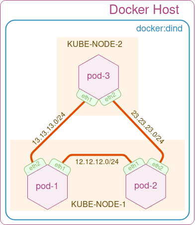
In this demo, we’ll build a simple triangle 3-node topology as shown in the figure above. We start by cloning the meshnet Github repository
git clone https://github.com/networkop/meshnet-cni.git && cd meshnet-cni
Next, create a local 3-node K8s cluster using kubeadm-dind-cluster, which uses docker-in-docker to simulate individual k8s nodes.
wget https://raw.githubusercontent.com/kubernetes-sigs/kubeadm-dind-cluster/master/fixed/dind-cluster-v1.11.sh
chmod +x ./dind-cluster-v1.11.sh
./dind-cluster-v1.11.sh up
The last command may take a few minutes to download all the required images. Once the K8s cluster is ready, we can start by deploying the private etcd cluster
export PATH="$HOME/.kubeadm-dind-cluster:$PATH"
kubectl create -f utils/etcd.yml
The ./tests directory already contains link databases for our 3-node test topology, ready to be uploaded to etcd:
ETCD_HOST=$(kubectl get service etcd-client -o json |  jq -r '.spec.clusterIP')
ENDPOINTS=$ETCD_HOST:2379

echo "Copying JSON files to kube-master"
sudo cp tests/*.json /var/lib/docker/volumes/kubeadm-dind-kube-master/_data/

echo "Copying etcdctl to kube-master"
sudo cp utils/etcdctl /var/lib/docker/volumes/kubeadm-dind-kube-master/_data/
docker exec kube-master cp /dind/etcdctl /usr/local/bin/

for pod in pod1 pod2 pod3
do
    # First cleanup any existing state
    docker exec -it kube-master sh -c "ETCDCTL_API=3 etcdctl --endpoints=$ENDPOINTS del --prefix=true \"/$pod\""

    # Next Update the links database
    docker exec -it kube-master sh -c "cat /dind/$pod.json | ETCDCTL_API=3 etcdctl --endpoints=$ENDPOINTS put /$pod/links"

    # Print the contents of links databse
    docker exec -it kube-master sh -c "ETCDCTL_API=3 etcdctl --endpoints=$ENDPOINTS get --prefix=true \"/$pod\""

done
The final missing piece is the meshnet daemonset, which installs the binary, configuration file and the meshnet daemon on every node.
kubectl create -f kube-meshnet.yml
The only thing that’s required now is the master plugin configuration update. Since different K8s clusters can use a different plugins, the configuration file installed by the daemonset contains a dummy value which needs to be overwritten. In our case, the kubeadm-dind-cluster we’ve installed should use a default bridge plugin which can be merged into our meshnet configuration file like this:
ETCD_HOST=$(kubectl get service etcd-client -o json |  jq -r '.spec.clusterIP')
for container in kube-master kube-node-1 kube-node-2
do
    # Merge the default CNI plugin with meshnet
    docker exec $container bash -c "jq  -s '.[1].delegate = (.[0]|del(.cniVersion))' /etc/cni/net.d/cni.conf /etc/cni/net.d/meshnet.conf  | jq .[1] > /etc/cni/net.d/00-meshnet.conf"
    docker exec $container bash -c "sed -i 's/ETCD_HOST/$ETCD_HOST/' /etc/cni/net.d/00-meshnet.conf"
done
Now meshnet CNI plugin is installed and configured and everything’s ready for us to create our test topology.
cat tests/2node.yml | kubectl create -f -
The following command will verify that the topology has been created and confirm that pods are scheduled to the correct nodes:
kubectl --namespace=default get pods -o wide  |  grep pod
pod1    1/1 Running 0   1m  10.244.2.7  kube-node-1
pod2    1/1 Running 0   1m  10.244.2.6  kube-node-1
pod3    1/1 Running 0   1m  10.244.3.5  kube-node-2
Finally, we can do a simple ping test to verify that we have connectivity between all 3 pods:
kubectl exec pod1 -- sudo ping -c 1 12.12.12.2
kubectl exec pod2 -- sudo ping -c 1 23.23.23.3
kubectl exec pod3 -- sudo ping -c 1 13.13.13.1
Coming up
The process demonstrated above is quite rigid and requires a lot of manual effort to create a required topology inside a K8s cluster. In the next post, we’ll have a look at k8s-topo - a simple tool that orchestrates most of the above steps - generates topology data and creates pods based on a simple YAML-based topology definition file.