SFC is another SDN feature that for a long time only used to be available in proprietary SDN solutions and that has recently become available in vanilla OpenStack. It serves as another proof that proprietary SDN solutions are losing the competitive edge, especially for Telco SDN/NFV use cases. Hopefully, by the end of this series of posts I’ll manage do demonstrate how to build a complete open-source solution that has feature parity (in terms of major networking features) with all the major proprietary data centre SDN platforms. But for now, let’s just focus on SFC.
SFC High-level overview
In most general terms, SFC refers to packet forwarding technique that uses more than just destination IP address to decide how to forward packets. In more specific terms, SFC refers to “steering” of traffic through a specific set of endpoints (a.k.a Service Functions), overriding the default destination-based forwarding. For those coming from a traditional networking background, think of SFC as a set of policy-based routing instances orchestrated from a central element (SDN controller). Typical use cases for SFC would be things like firewalling, IDS/IPS, proxying, NAT’ing, monitoring.
SFC is usually modelled as a directed (acyclic) graph, where the first and the last elements are the source and destination respectively and each vertex inside the graph represents a SF to be chained. IETF RFC7665 defines the reference architecture for SFC implementations and establishes some of the basic terminology. A simplified SFC architecture consists of the following main components:
- Classifier - a network element that matches and redirects traffic flows to a chain
- Service Function - an element responsible for packet processing
- Service Function Forwarder - a network element that forwards traffic to and from a directly connected SF
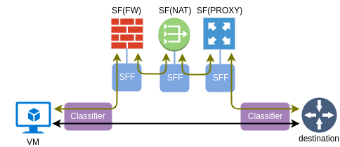
One important property of a SF is elasticity. More instances of the same type can be added to a pool of SF and SFF will load-balance the traffic between them. This is the reason why, as we’ll see in the next section, SFF treats connections to a SF as a group of ports rather than just a single port.
Insertion modes and implementation models
In legacy, pre-SDN environments SFs had no idea if they were a part of a service chain and network devices (routers and switches) had to “insert” the interesting traffic into the service function using one of the following two modes:
L2 mode is when SF is physically inserted between the source and destination inside a single broadcast domain, so traffic flows through a SF without any intervention from a switch. Example of this mode could be a firewall in transparent mode, physically connected between a switch and a default gateway router. All packets entering a SF have their original source and destination MAC addresses, which requires SF to be in promiscuous mode.
L3 mode is when a router overrides its default destination-based forwarding and redirects the interesting traffic to a SF. In legacy networks this could have been achieved with PBR or WCCP. In this case SF needs to be L2-attached to a router and all redirected packets have their destination MAC updated to that of a SF’s ingress interface.
Modern SDN networks make it really easy to modify forwarding behaviour of network elements, both physical and virtual. There is no need for policy-based routing or bump-in-the-wire designs anymore. When flow needs to be redirected to a SF on a virtual switch, all what’s required is a matching OpenFlow entry with a high enough priority. However redirecting traffic to a SF is just one part of the problem. Another part is how to make SFs smarter, to provide greater visibility of end-to-end service function path.
So far SFs have only been able to extract metadata from the packet itself. This limited the flexibility of SF logic and became computationally expensive in case many SFs need to access some L7 header information. Ideal way would be to have an additional header which can be used to read and write arbitrary information and pass it along the service function chain. RFC7665 defines requirements for “SFC Encapsulation” header which can be used to uniquely identify an instance of a chain as well as share metadata between all its elements. Neutron API refers to SFC encapsulation as correlation since its primary function is to identify a particular service function path. There are two implementations of SFC encapsulation in use today:
- MPLS - used by current OVS agent driver (as of Pike). This method does not provide any means to share metadata and serves only for SFP identification. It is intended as an interim solution until NSH becomes available upstream in OVS.
- NSH - complete implementation of SFC encapsulation defined in RFC7665. This method is currently implemented in Opendaylight where NSH is used as a shim between VXLAN-GPE and the encapsulated packet
It should be noted that the new approach with SFC encapsulation still allows for legacy, non-SFC-aware SFs to be chained. In this case SFC encapsulation is stripped off the packet by an “SFC proxy” before the packet is sent to the ingress port of a service function. All logical elements forming an SFC forwarding pipeline, including SFC proxy, Classifier and Forwarder, are implemented inside the same OVS bridges (br-int and br-tun) used by vanilla OVS-agent driver.
Configuring Neutron SFC
We’ll pick up where we left off in the previous post. All Neutron and ML2 configuration files have already been updated thanks to the enable_sfc="yes" setting in the global Kolla-Ansible configuration file. If not, you can change it in /etc/kolla/globals.yaml and re-run kolla-ansible deployment script.
First, let’s generate OpenStack credentials using a post-deployment script. We later can use a default bootstrap script to downloads the cirros image and set up some basic networking and security rules.
kolla-ansible post-deploy
source /etc/kolla/admin-openrc.sh
/usr/share/kolla-ansible/init-runonce
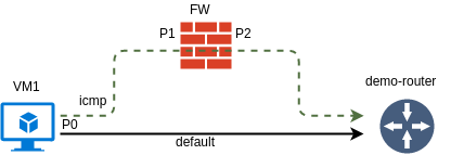
The goal for this post is to create a simple uni-directional SFC to steer the ICMP requests from VM1 to its default gateway through another VM that will be playing the role of a firewall.
The network was already created by the bootstrap script so all what we have to do is create a test VM. I’m creating a port in a separate step simply so that I can refer to it by name instead of UUID.
openstack port create --network demo-net P0
openstack server create --image cirros --flavor m1.tiny --port P0 VM1
I’ll go over all the necessary steps to setup SFC, but will only provide a brief explanation. Refer to the official OpenStack Networking Guide for a complete SFC configuration guide.
First, let’s create a FW VM with two ports - P1 and P2.
openstack port create --network demo-net P1
openstack port create --network demo-net P2
openstack server create --image cirros --flavor m1.tiny --port P1 --port P2 FW
Next, we need create an ingress/egress port pair and assign it to a port pair group. The default setting for correlation in a port pair (not shown) is none. That means that SFC encapsulation header (MPLS) will get stripped before the packet is sent to P1.
openstack sfc port pair create --ingress P1 --egress P2 PPAIR
openstack sfc port pair group create --port-pair PPAIR PPGROUP
Port pair group also allows to specify the L2-L4 headers which to use for load-balancing in OpenFlow groups, overriding the default behaviour described in the next section.
Another required element is a flow classifier. We will be redirecting ICMP traffic coming from VM1’s port P0
openstack sfc flow classifier create --protocol icmp --logical-source-port P0 FLOW-ICMP
Finally, we can tie together flow classifier with a previously created port pair group. The default setting for correlation (not shown again) in this case is mpls. That means that each chain will have its own unique MPLS label to be used as an SFC encapsulation.
openstack sfc port chain create --port-pair-group PPGROUP --flow-classifier FLOW-ICMP PCHAIN
That’s all the configuration needed to setup SFC. However if you login VM1’s console and try pinging default gateway, it will fail. Next, I’m going to give a quick demo of how to use a real-time network analyzer tool called Skydive to troubleshoot this issue.
Using Skydive to troubleshoot SFC
Skydive is a new open-source distributed network probing and traffic analyzing tool. It consists of a set of agents running on compute nodes, collecting topology and flow information and forwarding it to a central element for analysis.
The idea of using Skydive to analyze and track SFC is not new. In fact, for anyone interested in this topic I highly recommend the following blogpost. In my case I’ll show how to use Skydive from a more practical perspective - troubleshooting multiple SFC issues.
Skydive CLI client is available inside the skydive_analyzer container. We need to start an interactive bash session inside this container and set some environment variables:
docker exec -it skydive_analyzer bash
export SKYDIVE_ANALYZERS=192.168.133.100:8085
export SKYDIVE_USERNAME=admin
export SKYDIVE_PASSWORD=admin
The first thing we can do to troubleshoot is see if ICMP traffic is entering the ingress port of the FW VM. Based on the output of openstack port list command I know that P1 has got an IP of 10.0.0.8. Let’s if we can identify a tap port corresponding to P1:
skydive client topology query --gremlin "G.V().Has('Neutron.IPs', '10.0.0.8', 'Type', 'tun').Values('Neutron')"
{
  "IPs": "10.0.0.8",
  "NetworkID": "8eabb451-b026-417c-b54b-8e79ee6e71c3",
  "NetworkName": "demo-net",
  "PortID": "e6334df9-a5c4-4e86-a5f3-671760c2bbbe",
  "TenantID": "bd5829e0cb5b40b68ab4f8e7dc68b14d"
}
The output above proves that skydive agent has successfully read the configuration of the port and we can start a capture on that object to see any packets arriving on P1.
skydive client capture create --gremlin "G.V().Has('Neutron.IPs', '10.0.0.8', 'Type', 'tun')"
skydive client topology query --gremlin "G.V().Has('Neutron.IPs', '10.0.0.8', 'Type', 'tun').Flows().Has('Application','ICMPv4').Values('Metric.ABPackets')"
[
  7
]
If you watch the last command for several seconds you should see that the number in brackets is increasing. That means that packets are hitting the ingress port of the FW VM. Now let’s repeat the same test on egress port P2.
skydive client capture create --gremlin "G.V().Has('Neutron.IPs', '10.0.0.4', 'Type', 'tun')"
skydive client topology query --gremlin "G.V().Has('Neutron.IPs', '10.0.0.4', 'Type', 'tun').Flows()"
[]
The output above tells us that there are no packets coming out of the FW VM. This is expected since we haven’t done any changes to the blank cirros image to make it forward the packets between the two interfaces. If we examine the IP configuration of the FW VM, we would see that it doesn’t have an IP address configured on the second interface. We would also need to create a source-based routing policy to force all traffic from VM1 (10.0.0.6) to egress via interface eth2 and make sure IP forwarding is turned on. The following commands would need to be executed on FW VM:
sudo cirros-dhcpc up eth1
sudo ip rule add from 10.0.0.6 table default
sudo ip route add default via 10.0.0.1 dev eth1 table default
sudo sysctl -w net.ipv4.ip_forward=1
Having done that, we should see some packets coming out of egress port P2.
skydive client topology query --gremlin "G.V().Has('Neutron.IPs', '10.0.0.4', 'Type', 'tun').Flows().Has('Application','ICMPv4').Values('Metric.ABPackets')"
[
  7
]
However form the VM1’s perspective the ping is still failing. Next step would be to see if the packets are hitting the integration bridge that port P2 is attached to:
skydive client capture create --gremlin "G.V().Has('Neutron.IPs', '10.0.0.4', 'Type', 'veth')"
skydive client topology query --gremlin "G.V().Has('Neutron.IPs', '10.0.0.4', 'Type', 'veth').Flows()"
[]
No packets means they are getting dropped somewhere between the P2 and the integration bridge. This can only be done by security groups. In fact, source MAC/IP anti-spoofing is enabled by default which would only allow packets matching the source MAC/IP addresses assigned to P2 and would drop any packets coming from VM1’s IP address. The easiest fix would be to disable security groups for P2 completely:
openstack port set --no-security-group --disable-port-security P2
After this step the counters should start incrementing and the ping from VM1 to its default gateway is resumed.
skydive client topology query --gremlin "G.V().Has('Neutron.IPs', '10.0.0.4', 'Type', 'veth').Flows().Has('Application','ICMPv4').Values('Metric.ABPackets')"
[
  79
]
SFC implementation in OVS forwarding pipeline
The only element being affected in our case (both VM1 and FW are on the same compute node) is the integration bridge. Refer to my older post about vanilla OpenStack networking for a refresher of the vanilla OVS-agent architecture.
Normally, I would start by collecting all port and flow details from the integration bridge with the following commands:
ovs-ofctl dump-ports-desc br-int  | grep addr
ovs-ofctl dump-flows br-int | cut -d ',' -f3-
However, for the sake of brevity, I will omit the actual outputs and only show graphical representation of forwarding tables and packet flows. The tables below have two columns - first showing what is being matched and second showing the resulting action. Let’s start with the OpenFlow rules in an integration bridge before SFC is configured:
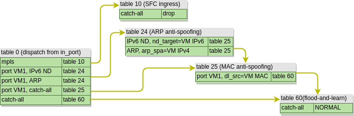
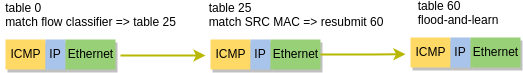
As we can see, the table structure is quite simple, since integration bridge mostly relies on data-plane MAC learning. A couple of MAC and ARP anti-spoofing tables will check the validity of a packet and send it to table 60 where NORMAL action will trigger the “flood-and-learn” behaviour. Therefore, an ICMP packet coming from VM1 will take the following path:
After we’ve configured SFC, the forwarding pipeline is changed and now looks like this:
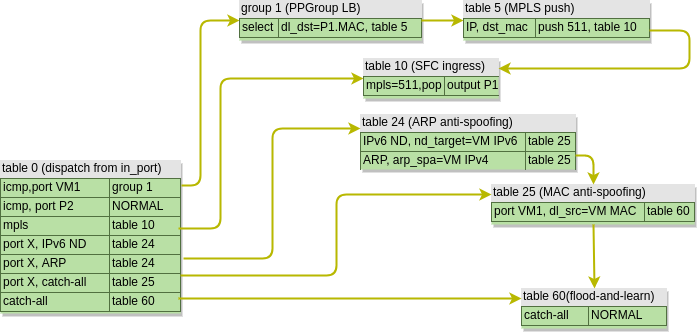
First, we can see that table 0 acts as a classifier, by redirecting the “interesting” packets towards group 1. This groups is an OpenFlow Group of type select, which load-balances traffic between multiple destinations. By default OVS will use a combination of L2-L4 header as described here to calculate a hash which determines the output bucket, similar to how per-flow load-balancing works in traditional routers and switches. This behaviour can be overridden with a specific set of headers in lb_fields setting of a port pair group.
In our case we’ve only got a single SF, so the packet gets its destination MAC updated to that of SF’s ingress port and is forwarded to a new table 5. Table 5 is where all packets destined for a SF are aggregated with a single MPLS label which uniquely identifies the service function path. The packet is then forwarded to table 10, which I’ve called SFC Ingress. This is where the packets are distributed to SF’s ingress ports based on the assigned MPLS label.
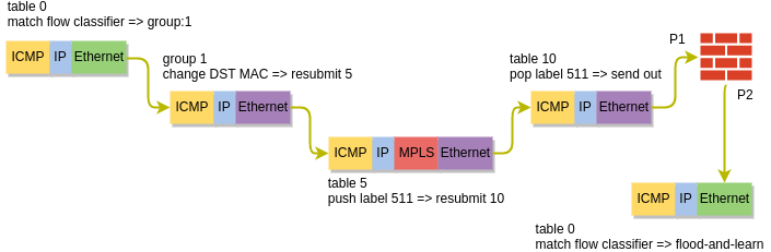
After being processed by a SF, the packet leaves the egress port and re-enters the integration bridge. This time table 0 knows that the packet has already been processed by a SF and, since the anti-spoofing rules have been disabled, simply floods the packet out of all ports in the same VLAN. The packet gets flooded to the tunnel bridge where it gets replicated and delivered to the qrouter sitting on the controller node as per the default behaviour.
Upcoming enhancements
SFC is a pretty vast topic and is still under active development. Some of the upcoming enhancement to the current implementation of SFC will include:
- NSH header for SFC correlation
- TAP functionality which can replace the separate Tap-as-a-service OpenStack project
- Service graphs allowing multiple chains to be interconnected to create more complex service chain scenarios
Coming Up
SFC is one of the major features in Telco SDN and, like many things, it’s not meant to be configured manually. In fact, Telco SDN have their own framework for management and orchestration of VNFs (a.k.a. VMs) and VNF forwarding graphs (a.k.a. SFCs) called ETSI MANO. As it is expected from a Telco standard, it abounds with acronyms and confuses the hell out of anyone who’s name is not on the list of authors or contributors. That’s why in the next post I will try to provide a brief overview of what Telco SDN is and use Tacker, a software implementation of NFVO and VNFM, to automatically build a firewall VNF and provision a SFC, similar to what has been done in this post manually.