In the previous post I’ve demonstrated a special-purpose CNI plugin for network simulations inside kubernetes called meshnet. I’ve shown how relatively easy it is to build a simple 3-node topology spread across multiple kubernetes nodes. However, when it comes to real-life large-scale topology simulations, using meshnet “as is” becomes problematic due to the following reasons:
- Uploading topology information into etcd requires a lot of manual effort.
- Any customisation like startup configuration injection or exposure of internal ports is still a manual process.
That is why I built k8s-topo - an orchestrator for network simulations inside kubernetes. It automates a lot of these manual steps and provides a simple and user-friendly interface to create networks of any size and configuration.
k8s-topo overview
k8s-topo is a Python script that creates network topologies inside k8s based on a simple YAML file. It uses syntax similar to docker-topo with a few modifications to account for the specifics of kubernetes environment. For instance, the following file is all what’s required to create and configure a simple 3-node topology:
etcd_port: 32379
links:
  - endpoints: ["host-1:eth1:12.12.12.1/24", "host-2:eth1:12.12.12.2/24"]
  - endpoints: ["host-1:eth2:13.13.13.1/24", "host-3:eth1:13.13.13.3/24"]
  - endpoints: ["host-2:eth2:23.23.23.2/24", "host-3:eth2:23.23.23.3/24"]
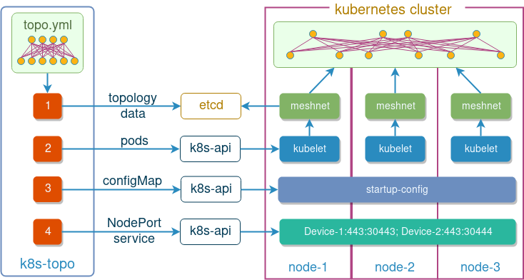
Behind the scenes it uses kubernetes and etcd python libraries to accomplish the following things:
- Upload topology information into etcd
- Create a pod for each network device mentioned in the topology file
- If present, mount devices startup configuration as volumes inside pods
- Expose internal HTTPs port as a NodePort service for every device
At the time of writing, k8s-topo supported three devices types, that get matched based on the device hostname prefix:
- Host device - an Alpine image, matched by prefix
host - cEOS device - an Arista cEOS image, matched by prefix
sw - Quagga device - an Alpine image with Quagga package installed, matched by prefix
qrtr
As an optional extra, k8s-topo can generate a D3.js graph that visualises the deployed network topology on an interactive web graph as will be shown later.
Installation
There are two main ways to install k8s-topo. The more traditional way will install k8s-topo as a python script on a local machine:
pip3 install git+https://github.com/networkop/k8s-topo.git
Another option is to install k8s-topo as a pod on top of a kubernetes cluster (it could be the same cluster that will be used for network simulations). For this option, we first need to build a k8s-topo docker image:
build.sh <dockerhub_username>
And then create a pod and its associated service:
kubectl create -f kube-k8s-topo.yml
Technically, it doesn’t matter where the k8s-topo is installed as long as it can access the k8s cluster and meshnet’s etcd service. However, for the sake of simplicity, examples below will assume hosted k8s install, which means that we only need to specify the etcd_port variable, leaving all others as default (e.g. etcd_host = localhost).
Random topology examples
To demonstrate capabilities of our orchestrator, I’ve written a random topology builder script that generates a uniform spanning tree graph, which is then used to create a topology definition YAML file along with a set of configuration files for each device. These configuration files accomplish two things:
- Configure a unique Loopback IP address in the
198.51.100.0/24range - Enable OSPF on all directly connected interfaces
The goal of this script is to be able to generate random large-scale network topologies that would be easy to test by simply ping-sweeping the range of all configured loopback addresses.
All following demos assume that meshnet CNI plugin has already been installed, as described in the previous post. Let’s start with a relatively small example of 50 cEOS containers.
Building a 50-node cEOS topology
Before we can start building cEOS topologies, we need to make the cEOS Docker image available in a private docker registry. Refer to the k8s-topo Github repository for a complete list of instructions.
First, we’ll generate a random 50-node topology. From inside the k8s-topo pod run:
./examples/builder/builder --prefix sw 50 0
Total number of links generated: 49
Prefix sw ensures that configured devices will be based on Arista cEOS image.
Next, we can use k8s-topo to create our random topology inside k8s:
./bin/k8s-topo --create examples/builder/random.yml
Some of the versions of cEOS don’t have the net.ipv4.ip_forward bit set which means no transit traffic will be allowed. In order to fix that, we can run the following command which modifies this setting on all running cEOS devices:
./bin/k8s-topo --eif examples/builder/random.yml
INFO:__main__:All pods are running, trying to enable ip forwarding for cEOS pods
INFO:__main__:All cEOS pods have IP forwarding enabled
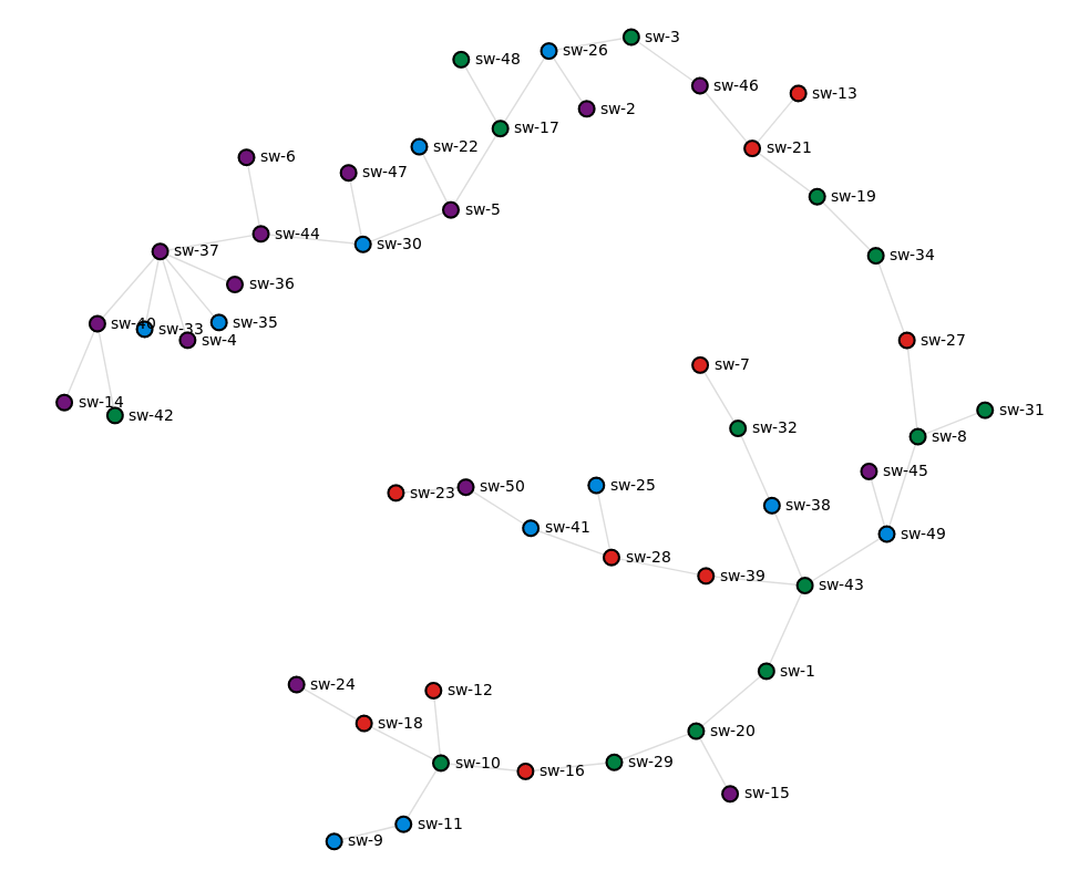
To be able see the generated topology we can run the following command, which creates a D3 graph and prints the URL we can use to access it.
/k8s-topo # ./bin/k8s-topo --graph examples/builder/random.yml
INFO:__main__:D3 graph created
INFO:__main__:URL: http://10.83.30.252:32080
The built-in nginx server renders a simple interactive web page with each device coloured according to the k8s node they are running on (in my case there are 4 nodes in total):
At this point we can run the ping-sweep test from any device to verify that we have complete end-to-end reachability:
# kubectl exec -it sw-1 bash
bash-4.3# for i in `seq 1 50`; do ping -c 1 -W 1 198.51.100.$i|grep from; done
64 bytes from 198.51.100.1: icmp_seq=1 ttl=64 time=0.061 ms
64 bytes from 198.51.100.2: icmp_seq=1 ttl=54 time=187 ms
64 bytes from 198.51.100.3: icmp_seq=1 ttl=56 time=139 ms
64 bytes from 198.51.100.4: icmp_seq=1 ttl=49 time=238 ms
64 bytes from 198.51.100.5: icmp_seq=1 ttl=53 time=189 ms
64 bytes from 198.51.100.6: icmp_seq=1 ttl=50 time=238 ms
64 bytes from 198.51.100.7: icmp_seq=1 ttl=61 time=71.6 ms
64 bytes from 198.51.100.8: icmp_seq=1 ttl=62 time=42.3 ms
64 bytes from 198.51.100.9: icmp_seq=1 ttl=59 time=91.0 ms
64 bytes from 198.51.100.10: icmp_seq=1 ttl=61 time=43.8 ms
64 bytes from 198.51.100.11: icmp_seq=1 ttl=60 time=60.8 ms
64 bytes from 198.51.100.12: icmp_seq=1 ttl=60 time=70.7 ms
64 bytes from 198.51.100.13: icmp_seq=1 ttl=57 time=134 ms
64 bytes from 198.51.100.14: icmp_seq=1 ttl=48 time=251 ms
64 bytes from 198.51.100.15: icmp_seq=1 ttl=63 time=27.8 ms
64 bytes from 198.51.100.16: icmp_seq=1 ttl=62 time=35.6 ms
64 bytes from 198.51.100.17: icmp_seq=1 ttl=54 time=182 ms
64 bytes from 198.51.100.18: icmp_seq=1 ttl=60 time=68.4 ms
64 bytes from 198.51.100.19: icmp_seq=1 ttl=59 time=97.9 ms
64 bytes from 198.51.100.20: icmp_seq=1 ttl=64 time=9.81 ms
64 bytes from 198.51.100.21: icmp_seq=1 ttl=58 time=114 ms
64 bytes from 198.51.100.22: icmp_seq=1 ttl=52 time=192 ms
64 bytes from 198.51.100.23: icmp_seq=1 ttl=59 time=102 ms
64 bytes from 198.51.100.24: icmp_seq=1 ttl=59 time=87.5 ms
64 bytes from 198.51.100.25: icmp_seq=1 ttl=61 time=66.7 ms
64 bytes from 198.51.100.26: icmp_seq=1 ttl=55 time=148 ms
64 bytes from 198.51.100.27: icmp_seq=1 ttl=61 time=60.6 ms
64 bytes from 198.51.100.28: icmp_seq=1 ttl=62 time=47.2 ms
64 bytes from 198.51.100.29: icmp_seq=1 ttl=63 time=18.8 ms
64 bytes from 198.51.100.30: icmp_seq=1 ttl=52 time=202 ms
64 bytes from 198.51.100.31: icmp_seq=1 ttl=61 time=49.2 ms
64 bytes from 198.51.100.32: icmp_seq=1 ttl=62 time=42.9 ms
64 bytes from 198.51.100.33: icmp_seq=1 ttl=49 time=252 ms
64 bytes from 198.51.100.34: icmp_seq=1 ttl=60 time=77.8 ms
64 bytes from 198.51.100.35: icmp_seq=1 ttl=49 time=217 ms
64 bytes from 198.51.100.36: icmp_seq=1 ttl=49 time=232 ms
64 bytes from 198.51.100.37: icmp_seq=1 ttl=50 time=218 ms
64 bytes from 198.51.100.38: icmp_seq=1 ttl=63 time=18.6 ms
64 bytes from 198.51.100.39: icmp_seq=1 ttl=63 time=24.6 ms
64 bytes from 198.51.100.40: icmp_seq=1 ttl=49 time=223 ms
64 bytes from 198.51.100.41: icmp_seq=1 ttl=61 time=48.4 ms
64 bytes from 198.51.100.42: icmp_seq=1 ttl=48 time=233 ms
64 bytes from 198.51.100.43: icmp_seq=1 ttl=64 time=11.0 ms
64 bytes from 198.51.100.44: icmp_seq=1 ttl=51 time=210 ms
64 bytes from 198.51.100.45: icmp_seq=1 ttl=62 time=51.6 ms
64 bytes from 198.51.100.46: icmp_seq=1 ttl=57 time=125 ms
64 bytes from 198.51.100.47: icmp_seq=1 ttl=51 time=222 ms
64 bytes from 198.51.100.48: icmp_seq=1 ttl=53 time=181 ms
64 bytes from 198.51.100.49: icmp_seq=1 ttl=63 time=33.8 ms
64 bytes from 198.51.100.50: icmp_seq=1 ttl=60 time=71.1 ms
This test proves that sw-1 can reach the loopback IP of every other device in the topology and, since the topology does not have any redundant links, also proves that k8s-topo, together with meshnet, have interconnected all devices correctly. If we had incorrectly connected at least one of the links, the OSPF adjacency would not have formed (due to incorrect source IP in the OSPF hello on NBMA network) and some of the pings would have failed.
To destroy the network topology and clean-up any state stored in etcd, we can run the following command:
./bin/k8s-topo --destroy examples/builder/random.yml
Building a 250-node Quagga topology
Now let’s take this up a notch and test a 250-node topology built out of Quagga containers. Once again, we’ll use the builder script to generate a random spanning-tree graph and create all the required configuration files:
./examples/builder/builder 250 0
Total number of links generated: 249
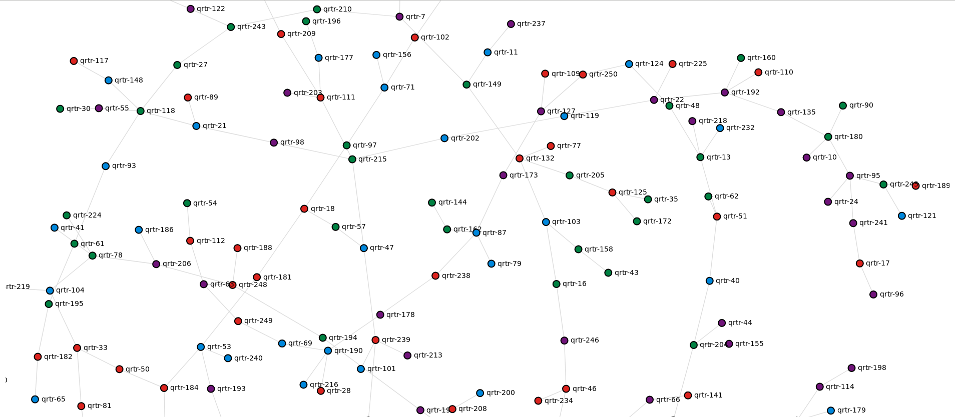
Now we can spin-up our 250-node topology:
./bin/k8s-topo --create examples/builder/random.yml
The generated graph is not as neat anymore but can be very handy when troubleshooting connectivity issues between different parts of topology
Finally, we can do a loopback ping-sweep test from any random node in our topology to prove that everything has been interconnected correctly:
# kubectl exec -it qrtr-19 sh
/ # for i in `seq 1 250`; do ping -c 1 -W 1 198.51.100.$i|grep from; done
64 bytes from 198.51.100.1: seq=0 ttl=39 time=2.867 ms
64 bytes from 198.51.100.2: seq=0 ttl=42 time=1.979 ms
64 bytes from 198.51.100.3: seq=0 ttl=23 time=3.339 ms
64 bytes from 198.51.100.4: seq=0 ttl=37 time=2.348 ms
64 bytes from 198.51.100.5: seq=0 ttl=52 time=1.277 ms
64 bytes from 198.51.100.6: seq=0 ttl=33 time=2.662 ms
64 bytes from 198.51.100.7: seq=0 ttl=49 time=1.054 ms
64 bytes from 198.51.100.8: seq=0 ttl=40 time=2.320 ms
64 bytes from 198.51.100.9: seq=0 ttl=48 time=1.127 ms
64 bytes from 198.51.100.10: seq=0 ttl=61 time=0.425 ms
<...>
64 bytes from 198.51.100.240: seq=0 ttl=50 time=1.101 ms
64 bytes from 198.51.100.241: seq=0 ttl=62 time=0.254 ms
64 bytes from 198.51.100.242: seq=0 ttl=35 time=2.288 ms
64 bytes from 198.51.100.243: seq=0 ttl=51 time=0.939 ms
64 bytes from 198.51.100.244: seq=0 ttl=32 time=2.468 ms
64 bytes from 198.51.100.245: seq=0 ttl=64 time=0.523 ms
64 bytes from 198.51.100.246: seq=0 ttl=44 time=1.452 ms
64 bytes from 198.51.100.247: seq=0 ttl=41 time=1.705 ms
64 bytes from 198.51.100.248: seq=0 ttl=44 time=1.429 ms
64 bytes from 198.51.100.249: seq=0 ttl=42 time=1.722 ms
64 bytes from 198.51.100.250: seq=0 ttl=34 time=1.968 ms
Conclusion
For a very long time, when building real-life virtual network topologies, we had to compromise on the number of real network devices that can be simulated. This led to topology simplification and often resulted in parts of the real network topologies either missed or collapsed into a single virtual device. With k8s-topo and meshnet CNI plugin, we can now build one-to-one replicas of physical network topologies of any size and complexity, without sacrificing the level of detail.