In the previous post I’ve demonstrated how to build virtual network topologies on top of Kubernetes with the help of meshnet-cni plugin. As an example, I’ve shown topologies with 50 cEOS instances and 250 Quagga nodes. In both of these examples virtual network devices were running natively inside Docker containers, meaning they were running as (a set of) processes directly attached to the TCP/IP stack of the network namespace provided by the k8s pod. This works well for the native docker images, however, the overwhelming majority of virtual network devices are still being released as VMs. In addition to that, some of them require more than one VM and some special bootstrapping before they can they can be used for the first time. This means that in order to perform true multi-vendor network simulations, we need to find a way to run VMs inside containers, which, despite the seeming absurdity, is quite a common thing to do.
Option 1 - kubevirt
Kubevirt is a very popular project that provides the ability to run VMs inside k8s. It uses the power of Custom Resource Definitions to extend the native k8s API to allow the definition of VM parameters (libvirt domainxml) same as you would do for any other native k8s resource. It runs each VM inside the containerised KVM hypervisor, attaching them to libvirt-managed networking stack.
However, since kubevirt is built for general-purpose VMs, making it work with virtual network devices requires a lot of work. Most of the bootstrapping tasks like startup configuration injection, disabling of ZTP and various OS-specific quirks like serial/video output selection for CSR or VCP reboot for VMX, would still need to be done after the pod is created. None of that is a major obstacle and hopefully virtual network OSs will also adopt standard server bootstrapping techniques like cloud-init, but until that happens we’d want to deal with those problems with as little effort as possible, which is where vrnetlab comes to the rescue.
Option 2 - vrnetlab
vrnetlab is an open-source project that runs virtual network devices in Docker containers for “convenient labbing, development and testing”. At the time of writing, vrnetlab supported close to a dozen of virtual NOSs across most of the major vendors:
- Cisco - CSR, NXOS and XRV
- Juniper - VMX and vQFX
- Arista - vEOS
- Nokia - VSR/SROS
- Huawei - VRP
- HP - VSR1000
- Mikrotik - ROS
- OpenWRT
The way I see it, vrnetlab accomplishes two things:
- Automates generation of Docker images from the original qcow2 or vmdk files
- Interconnect virtual routers based on the user-defined topology
The above two things are loosely coupled and although vrnetlab docker images are built to expose VM’s network interfaces as TCP sockets (stitched together by the topology machine later), it’s still possible to use them for other purposes. My specific interest was to try and run vrnetlab images inside the kubernetes cluster with networking orchestrated by meshnet-cni.
Patching vrnetlab
Making it work turned out to be easier than I thought. All that I had to do was introduce a flag to control how the network interfaces are connected and add a special case for meshnet. This is a high-level logic of how the patch works:
- vrnetlab images now accept an additional optional argument called
--meshnet - this argument controls whether to connect VM to native docker interfaces or use the default TCP socket option
- for every ethernet interface inside a container a bridge is created, enslaving this interface
- VM is now attached to each one of those bridges instead of the TCP sockets
This patch is still in a pull request waiting to be tested so for the rest of this post I’ll be using my fork, which has all of these changes already merged.
Demo
I’ll assume that the Kubernetes cluster is already installed along with both meshnet-cni and k8s-topo. For demonstration purposes, I’ll use a random topology with a mix of Juniper vMX (v17.2R1.13) and Cisco CSR1000v (v16.04.01) devices, both built using vrnetlab.
Building images
The first thing to do is download the patched version of vrnetlab:
git clone --depth 1 https://github.com/networkop/vrnetlab.git
Now copy both images into their respective directories and for each one of them run:
make docker-image
The expected result is to have two local images that look something like this:
core@node1 ~ $ docker images | grep vrnetlab
vrnetlab/vr-csr   16.04.01    b701e7811221   2 days ago   1.76GB
vrnetlab/vr-vmx   17.2R1.13   9a6af68dde78   2 days ago   4.7GB
Uploading images to a private registry
Now we need to make these images available to all nodes in the cluster and the easiest way to do that is to upload them into a private docker registry. So from a node with cluster credentials, create a local registry:
kubectl create -f https://raw.githubusercontent.com/networkop/k8s-topo/master/examples/docker-registry/docker-registry.yml
Now use the service IP to create the registry URL variable:
export REGISTRY=$(kubectl get service docker-registry -o json | jq -r '.spec.clusterIP'):5000
Assuming both images are stored on the localhost do:
docker tag vrnetlab/vr-csr:16.04.01 $REGISTRY/vr-csr:16.04.01
docker push $REGISTRY/vr-csr:16.04.01

docker tag vrnetlab/vr-vmx:17.2R1.13 $REGISTRY/vr-vmx:17.2R1.13
docker push $REGISTRY/vr-vmx:17.2R1.13
Once uploaded, we can query the following registry URL to confirm that:
curl -X GET http://$REGISTRY/v2/_catalog
{"repositories":["vr-csr","vr-vmx"]}
Creating the network topology
First, connect to the k8s-topo pod:
kubectl exec -it k8s-topo sh
Create the image URL environment variables for both CSR and vMX. These will later be used by the k8s-topo script.
export REGISTRY=$(kubectl get service docker-registry -o json | jq -r '.spec.clusterIP'):5000
export CSR_IMAGE=$REGISTRY/vr-csr:16.04.01
export VMX_IMAGE=$REGISTRY/vr-vmx:17.2R1.13
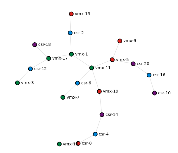
Generate a random spanning-tree topology with a mix of vmx and csr devices. The prefix argument accepts a list of one or more prefixes which determine the image to be used for the device.
./examples/builder/builder 20 0 --prefix vmx csr
Total number of links generated: 19
Now use the k8s-topo script to create the topology and corresponding services:
./bin/k8s-topo --create examples/builder/random.yml
INFO:__main__:All data has been uploaded to etcd
INFO:__main__:All pods have been created successfully
INFO:__main__:
 alias csr-8='ssh -p 30010 vrnetlab@localhost'
 alias vmx-15='ssh -p 30014 vrnetlab@localhost'
 alias csr-4='ssh -p 30008 vrnetlab@localhost'
 alias csr-14='ssh -p 30003 vrnetlab@localhost'
 alias vmx-19='ssh -p 30016 vrnetlab@localhost'
 alias vmx-11='ssh -p 30012 vrnetlab@localhost'
 alias vmx-5='ssh -p 30018 vrnetlab@localhost'
 alias csr-20='ssh -p 30007 vrnetlab@localhost'
 alias csr-16='ssh -p 30004 vrnetlab@localhost'
 alias csr-10='ssh -p 30001 vrnetlab@localhost'
 alias vmx-1='ssh -p 30011 vrnetlab@localhost'
 alias csr-2='ssh -p 30006 vrnetlab@localhost'
 alias vmx-13='ssh -p 30013 vrnetlab@localhost'
 alias vmx-17='ssh -p 30015 vrnetlab@localhost'
 alias csr-12='ssh -p 30002 vrnetlab@localhost'
 alias csr-18='ssh -p 30005 vrnetlab@localhost'
 alias csr-6='ssh -p 30009 vrnetlab@localhost'
 alias vmx-7='ssh -p 30019 vrnetlab@localhost'
 alias vmx-9='ssh -p 30020 vrnetlab@localhost'
 alias vmx-3='ssh -p 30017 vrnetlab@localhost'
If LLDP is required between nodes, it can be enabled with this command:
./bin/k8s-topo --lldp examples/builder/random.yml
Verification
Finally, it’s time to verify the connectivity between the nodes. Since all of the devices come up with minimal configuration, I’ll pick a random pair to demonstrate the LLDP and IP connectivity:
$ vmx-11
Warning: Permanently added '[localhost]:30012' (ECDSA) to the list of known hosts.
Password:
--- JUNOS 17.2R1.13 Kernel 64-bit  JNPR-10.3-20170523.350481_build
vrnetlab> configure
Entering configuration mode
vrnetlab# set interfaces ge-0/0/3 unit 0 family inet address 12.12.12.1/24
vrnetlab# set protocols lldp interface all
vrnetlab# set protocols lldp port-id-subtype interface-name
vrnetlab# commit and-quit
commit complete
Exiting configuration mode
And now configure the other side of the link:
$ csr-6
Warning: Permanently added '[localhost]:30009' (RSA) to the list of known hosts.
Password:

csr1000v#conf t
Enter configuration commands, one per line.  End with CNTL/Z.
csr1000v(config)#lldp run
csr1000v(config)#int gigabitEthernet 2
csr1000v(config-if)#ip address 12.12.12.2 255.255.255.0
csr1000v(config-if)#no shut
csr1000v(config-if)#exit
At this point, both devices should be able to ping and see each other as LLDP neighbors.
csr1000v#sh lldp neighbors
Capability codes:
    (R) Router, (B) Bridge, (T) Telephone, (C) DOCSIS Cable Device
    (W) WLAN Access Point, (P) Repeater, (S) Station, (O) Other

Device ID           Local Intf     Hold-time  Capability      Port ID
0005.86f0.f7c0      Gi2            120        B,R             ge-0/0/3

Total entries displayed: 1

csr1000v#ping 12.12.12.1
Type escape sequence to abort.
Sending 5, 100-byte ICMP Echos to 12.12.12.1, timeout is 2 seconds:
!!!!!
Success rate is 100 percent (5/5), round-trip min/avg/max = 2/8/18 ms
csr1000v#