In September 2019 I had the honour to present at Open Networking Summit in Antwerp. My talk was about meshnet CNI plugin, k8s-topo orchestrator and how to use them for large-scale network simulations in Kubernetes. During the same conference, I attended a talk about Network Service Mesh and its new kernel-based forwarding dataplane which had a lot of similarities with the work that I’ve done for meshnet. Having had a chat with the presenters, we’ve decided that it would be interesting to try and implement a meshnet-like functionality with NSM. In this post, I’ll try to document some of the findings and results of my research.
Network Service Mesh Introduction
NSM is a CNCF project aimed at providing service mesh-like capabilities for L2/L3 traffic. In the context of Kubernetes, NSM’s role is to interconnect pods and setup the underlying forwarding, which involves creating new interfaces, allocating IPs and configuring pod’s routing table. The main use cases are cloud-native network functions (e.g. 5G), service function chaining and any containerised applications that may need to talk over non-standard protocols. Similar to traditional service meshes, the intended functionality is achieved by injecting sidecar containers that communicate with a distributed control plane of network service managers, deployed as a daemonset.
I’ll try to avoid repeating NSM’s theory here and instead refer my readers to the official documentation and a very good introductory slide deck. There are a few concepts, however, that are critical to the understanding of this blogpost, that I’ll mention here briefly:
- Network Services are built around a client-server model - a client receives a service from an endpoint (server).
- Both client and endpoint are implemented as containers and interact with local control plane agents over a gRPC-based API.
- Typically, a client would request a service with
ns.networkservicemesh.ioannotation, which gets matched by a mutating webhook responsible for injecting an init container. - Endpoints, being designed specifically to provide network services, have endpoint container statically defined as a sidecar (unless they natively implement NSM’s SDK).
- One important distinction between client and endpoint sidecars is that the former is an init container (runs to completion at pod create time) and the latter is a normal sidecar which allows service reconfiguration at runtime.
- All client and endpoint configurations get passed as environment variables to the respective containers either dynamically (client) or statically (endpoint).
Given all of the above, this is how you’d use NSM to create a point-to-point link between any two pods.
Using NSM to create links between pods
First, we need to decide which side of the link will be a client and which will be an endpoint. This is where we’ll abuse NSM’s concepts for the first time as it really doesn’t matter how this allocation takes place. For a normal network service, it’s fairly easy to identify and map client/server roles, however, for topology simulations they can be assigned arbitrarily as both sides of the link are virtually equivalent.
The next thing we need to do is statically add sidecar containers not only to the endpoint side of the link but to the client as well. This is another abuse of NSM’s intended mode of operation, where a client init container gets injected automatically by the webhook. The reason for that is that the init container will block until its network service request gets accepted, which may create a circular dependency if client/endpoint roles are assigned arbitrarily, as discussed above.
The resulting “endpoint” side of the link will have the following pod manifest. The NSE sidecar container will read the environment variables and use NSM’s SDK to register itself with a p2p network service with a device=device-2 label.
apiVersion: v1
kind: Pod
metadata:
  name: device-2
spec:
  containers:
  - image: alpine:latest
    command: ["tail", "-f", "/dev/null"]
    name: alpine
  - name: nse-sidecar
    image: networkservicemesh/topology-sidecar-nse:master
    env:
    - name: ENDPOINT_NETWORK_SERVICE
      value: "p2p"
    - name: ENDPOINT_LABELS
      value: "device=device-2"
    - name: IP_ADDRESS
      value: "10.60.1.0/24"
    resources:
      limits:
        networkservicemesh.io/socket: "1"
When a local control plane agent receives the above registration request, it will create a new k8s NetworkServiceEndpoint resource, effectively letting all the other agents know where to find this particular service endpoint (in this case it’s the k8s node called nsm-control-plane). Note that the below resource is managed by NSM’s control plane and should not be created by the user:
apiVersion: networkservicemesh.io/v1alpha1
kind: NetworkServiceEndpoint
metadata:
  generateName: p2p
  labels:
    device: device-2
    networkservicename: p2p
  name: p2ppdp2d
spec:
  networkservicename: p2p
  nsmname: nsm-control-plane
  payload: IP
status:
  state: RUNNING
The next bit is the manifest of the network service itself. Its goal is to establish a relationship between multiple clients and endpoints of a service by matching their network service labels.
apiVersion: networkservicemesh.io/v1alpha1
kind: NetworkService
metadata:
  name: p2p
spec:
  matches:
  - match:
    sourceSelector:
      link: net-0
    route:
    - destination:
      destinationSelector:
        device: device-2
  payload: IP
The final bit is the “client” side of the link which will have the following pod manifest. Note that the format of NS_NETWORKSERVICEMESH_IO variable is the same as the one used in annotations and can be read as “client requesting a p2p service with two labels (link=net-0 and peerif=eth21) and wants to connect to it over a local interface called eth12”.
apiVersion: v1
kind: Pod
metadata:
  name: device-1
spec:
  containers:
  - image: alpine:latest
    command: ["tail", "-f", "/dev/null"]
    name: alpine
  - name: nsc-sidecar
    image: networkservicemesh/topology-sidecar-nsc:master
    env:
    - name: NS_NETWORKSERVICEMESH_IO
      value: p2p/eth12?link=net-0&peerif=eth21
    resources:
      limits:
        networkservicemesh.io/socket: "1"
The client’s sidecar will read the above environment variable and send a connection request to the local control plane agent which will perform the following sequence of steps:
- Locate a network service called
p2p. - Find a match based on client-provided labels (
link=net-0). - Try to find a matching network service endpoint (
device=device-2). - Contact the remote agent hosting a matching endpoint (found in NSE CRDs) and relay the connection request.
- If the request gets accepted by the endpoint, instruct the local forwarding agent to set up pod’s networking.
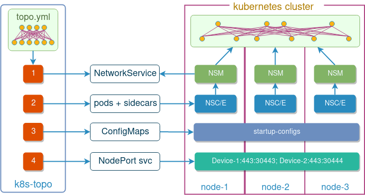
Topology orchestration with k8s-topo
Looking at the above manifests, it’s clear that writing them manually, even for smaller topologies, can be a serious burden. That’s why I’ve adapted the k8s-topo tool that I’ve written originally for meshnet-cni to produce and instantiate NSM-compliant manifest based on a single light-weight topology YAML file. The only thing that’s needed to make it work with NSM is to add a nsm: true to the top of the file, e.g.:
nsm: true
links:
  - endpoints: ["device-1:eth12", "device-2:eth21"]
Behind the scenes, k8s-topo will create the required network service manifest and configure all pods with correct sidecars and variables. As an added bonus, it will still attempt to inject startup configs and expose ports as described here.
NSM vs Meshnet for network simulations
In the context of virtual network simulations, both NSM and meshnet-cni can perform similar functions, however, their implementation and modes of operation are rather different. Here are the main distinctions of a CNI plugin approach:
- All networking is setup BEFORE the pod is started.
- CNI plugin does all the work so there’s no need for sidecar containers.
- A very thin code base for a very specific use case.
And here are some of the distinctions of an NSM-based approach:
- All networking is setup AFTER the pod is started.
- This does come with a requirement for a sidecar container, but potentially allows for runtime reconfiguration.
- No requirement for a CNI plugin at all.
- More generic use cases are possible.
In the end, none of the options limit the currently available featureset of k8s-topo and the choice can be done based on the characteristics of an individual environment, e.g. if it’s a managed k8s from GCP (GKE) or Azure (AKS) then most likely you’ll be running kubenet and won’t have an option to install any CNI plugin at all, in which case NSM can be the only available solution.
Demo
Now it’s demo time and I’ll show how to use k8s-topo together with NSM to build a 10-node virtual router topology. We start by spinning up a local kind kubernetes cluster and installing NSM on it:
git clone https://github.com/networkservicemesh/networkservicemesh
cd networkservicemesh
make helm-init
SPIRE_ENABLED=false INSECURE=true FORWARDING_PLANE=kernel make helm-install-nsm
Next, we install the k8s-topo deployment and connect to the pod running it:
kubectl create -f https://raw.githubusercontent.com/networkop/k8s-topo/master/manifest.yml
kubectl exec -it deploy/k8s-topo -- sh
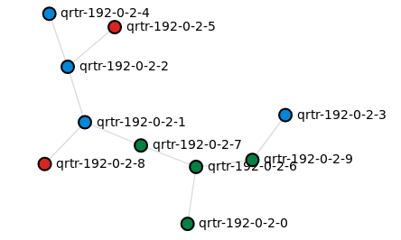
For demonstration purposes I’ll use a random 10-node tree topology generated using a loop-erased random walk:
./examples/builder/builder 10 0
The only thing needed to make it work with NSM is set the nsm flag to true:
sed -i '$ a\nsm: true' ./examples/builder/random.yml
Now everything’s ready for us to instantiate the topology inside k8s:
k8s-topo --create ./examples/builder/random.yml
Once all the pods are up, we can issue a ping from one of the routers to every other router in the topology and confirm the connectivity between their loopback IPs:
for i in `seq 0 9`; do (kubectl exec qrtr-192-0-2-0 -c router -- ping -c 1 192.0.2.$i|grep loss); done

1 packets transmitted, 1 packets received, 0% packet loss
1 packets transmitted, 1 packets received, 0% packet loss
1 packets transmitted, 1 packets received, 0% packet loss
1 packets transmitted, 1 packets received, 0% packet loss
1 packets transmitted, 1 packets received, 0% packet loss
1 packets transmitted, 1 packets received, 0% packet loss
1 packets transmitted, 1 packets received, 0% packet loss
1 packets transmitted, 1 packets received, 0% packet loss
1 packets transmitted, 1 packets received, 0% packet loss
1 packets transmitted, 1 packets received, 0% packet loss
If you want to have a look at your topology, it’s possible to make k8s-topo generate a D3 graph of all pods and their connections and view it in the browser:
k8s-topo --graph ./examples/builder/random.yml
INFO:__main__:D3 graph created
INFO:__main__:URL: http://172.17.0.3:30000